




3D AOI in SMT Production: Role and Benefits
3D AOI in SMT production gives manufacturers a fast, accurate way to inspect printed circuit boards for soldering defects. AOI stands for automatic optical inspection. The system uses cameras and optical technology to scan the PCB, capture images, and compare every solder joint with qualified parameters in its database.
A 3D AOI adds height measurement to the normal two-dimensional image. This allows the system to measure solder volume, component lead height, and pad coplanarity, which are difficult to check with a standard 2D camera.
This guide explains the role of 3D AOI on an SMT production line and how it improves process control and final PCBA quality.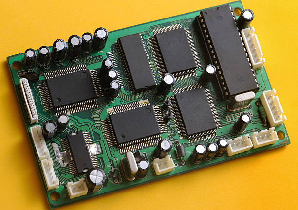
How AOI Inspects a Board
During automatic inspection, the AOI machine scans the PCB with cameras and collects an image. The image processing software compares the tested solder joints with the acceptable parameters stored in the machine database.
Defects found on the PCB are marked on the display or identified by an automatic marking system. Repair personnel can then view the defect location and correct the board.
A 3D system adds a structured light projector or multiple camera angles so the software can create a height map of the board. The height map shows solder volume and component standoff that are not visible in a flat image.
This makes the inspection result more reliable and reduces the number of defects that pass into later assembly steps.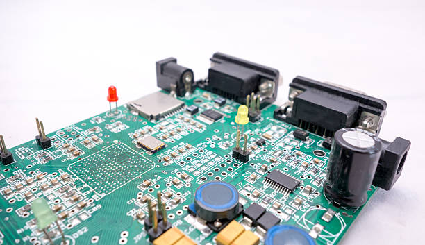
What 3D AOI Can Detect
3D AOI can detect missing components, wrong parts, reversed polarity, shifted components, and tombstoned chips. It also checks the solder joint shape after reflow.
The height data allows the system to identify insufficient solder, excess solder, and solder bridges more accurately. It can also measure whether an IC lead is lifted from its pad.
For bottom-terminated components and fine-pitch packages, the height measurement helps confirm that the part is seated correctly before reflow.
By combining image contrast with height information, 3D AOI reduces false calls while maintaining a high probability of defect detection.
Where AOI Is Used on the Line
AOI can be placed at several positions on an SMT production line. After solder paste printing, it can check the paste volume and alignment before components are placed.
After component placement and before reflow, AOI can detect missing parts, wrong polarity, and shifted components while they can still be corrected easily.
After reflow soldering, AOI inspects the final solder joints. This position catches defects such as bridges, opens, insufficient solder, and tombstoning that appear after the solder melts.
Some lines use two or three AOI systems to control every critical process step.
Role in Early Defect Detection
AOIs are used as a defect reduction tool. They find and eliminate errors early in the assembly process, before a bad board reaches the next assembly stage.
Early detection avoids adding expensive assembly time to a board that already has a fatal fault. It also prevents a defective board from being covered by another component or process step.
Because AOI detects defects before final test, it reduces repair cost and avoids scrapping boards that cannot be repaired.
Early process control also makes it possible to stop the line quickly when a placement machine or printer begins to drift.
Why Manual Inspection Is Not Enough
Before AOI, PCB inspection was performed by operators using microscopes at workstations. This process could check the surface for missing components, incorrect paste, and solder defects, but it had important limitations.
Manual inspection is easy for a small board with a few components. When the board is large and contains thousands of parts, an operator cannot inspect every joint with consistent accuracy.
Eye fatigue, lighting differences, and personal judgment make manual inspection less reliable. Long inspection times also reduce production capacity.
3D AOI provides a repeatable inspection standard that is not affected by shift changes or operator fatigue.
Benefits of 3D Height Measurement
A two-dimensional AOI sees the board from one angle and measures differences in color and contrast. A 3D AOI measures the actual height of every feature on the board.
Height measurement improves solder paste inspection because the volume of paste can be calculated from its area and height. This is more reliable than comparing only the darkness of the paste image.
For QFP and connector leads, 3D inspection can measure lead coplanarity and detect a lead that is bent above the solder pad.
The height data also helps the system distinguish a real solder bridge from a shadow or reflection on the board surface.
Handling Different Board Sizes
As circuit board sizes change, production lines need an inspection system that can handle both high-density fine-pitch boards and low-density large boards.
A modern 3D AOI can change its field of view and inspection resolution according to the board type. It can inspect small board areas with high magnification and then move to the next area automatically.
The system program is generated from CAD data and can be optimized for each product. This allows the factory to switch between board sizes without reducing inspection quality.
Board warpage can also be handled better by 3D systems because the height map shows the actual surface rather than assuming a flat board.
Online Inspection and Production Speed
3D AOI can be integrated into the SMT line as an online inspection station. The board is inspected while it moves along the conveyor, so production does not stop for offline analysis.
High-speed image processing and lighting systems allow the machine to inspect each frame within the line cycle time. The inspection result is displayed immediately so that defects can be corrected while the process is still running.
Online inspection is essential for high-volume products where manual sampling would leave too many defects undetected.
The AOI system can also send defect data to the factory control system for real-time process monitoring.
Process Control and Yield Improvement
3D AOI provides more than a pass or fail result. It collects data about the position, type, and size of every defect found on the board.
This data can be used with SPC to show whether a process is stable. If the number of insufficient solder joints increases, the engineer can check the stencil, paste, or profile before a large lot is affected.
Defect trends can be compared with placement machine data, printer data, and reflow oven data to find the root cause.
Improving the process from AOI data increases first-pass yield and reduces the cost of repair.
Combining AOI With X-ray and Electrical Test
3D AOI inspects visible solder and component features, but it cannot see under a BGA package. X-ray inspection should be used for hidden solder joints.
Electrical testing is still required to verify component values and circuit function. The combination of AOI, X-ray, ICT, and functional test gives complete quality coverage.
The inspection results should be stored with the production lot. This helps the factory trace a field failure back to the exact board and process condition.
A qualified SMT PCB assembly service should use 3D AOI at the process steps where visible defects can be corrected most cheaply.
The AOI program should be reviewed during PCB design and layout so that component markings and pad geometry support reliable inspection.
Process data from AOI should be part of the quality management system and should be combined with PCBA testing results.
A professional PCB assembly partner should document the inspection method and report defect trends to the customer when requested.
An AOI program should be built from the actual board data and then optimized during first article production. The engineer can define inspection regions for each component, adjust the acceptable solder height, and choose the defect categories that matter for the product. A program that is too strict will create many false calls, while a program that is too loose will allow real defects to pass.
3D AOI systems must be calibrated and cleaned regularly. Camera focus, lighting intensity, and conveyor position affect the height measurement, so a daily calibration check is recommended before high-volume production. The calibration standard should be traceable and the result should be stored in the maintenance log.
Operator training is another important part of the process. The repair operator must be able to read the AOI image, identify the component location, and decide whether a flagged area is a real defect. A clear standard operating procedure should describe when to rework, when to accept, and when to send the board for X-ray or electrical review.
The combination of a well-optimized program, a calibrated machine, and trained operators gives 3D AOI its greatest value on the SMT line. It turns the inspection system into a process improvement tool instead of only a final quality gate.
Conclusion
3D AOI in SMT production gives manufacturers a powerful tool for finding soldering and placement defects quickly. Its height measurement capability improves solder volume, lead, and bridge detection.
Early detection, repeatable standards, and statistical process data help reduce repair cost and improve first-pass yield.
When 3D AOI is combined with X-ray and electrical testing, the SMT line can deliver consistent, high-quality PCBA products.


