High Volume PCB Assembly Guide: SMT and Through-Hole Soldering
Why High Volume PCB Assembly Demands a Controlled Process
High volume PCB assembly turns a proven design into thousands of reliable boards with the same quality every day. When the quantity is large, the soldering process stops being a single event and becomes a production system: the solder paste, the placement machines, the ovens, and the inspection stations must repeat the same result board after board. Small variations that are invisible in a prototype run can multiply into field failures when they repeat across a whole batch.
Most volume production today mixes two component technologies. Surface mount parts dominate because they are small, cheap, and fast to place, while through-hole parts remain for connectors, power devices, and components that must resist mechanical stress. Understanding how each technology is soldered, and where each one belongs, is the foundation of an assembly line that ships on time without quality surprises.
Surface Mount vs Through-Hole Components in Volume
Surface mount technology became the main packaging form on modern boards for practical reasons. SMT parts need no drilled holes, so they are smaller and allow more circuits on the same board area. Smaller parts bring lower manufacturing cost, and shorter conductor paths reduce the signal travel time, which improves electrical performance at high speed. For passive components such as resistors and capacitors, surface mount packaging has almost completely replaced the older through-hole versions.
Through-hole parts still earn their place in high-power and high-stress positions. Power components contain more metal and achieve better solder joints with leads that pass through the board, and the stronger mechanical connection supports high voltage, thermal cycling, and vibration. Connectors, switches, and other interface parts that face constant physical stress during normal use are usually through-hole for strength, and some large components simply have no practical surface mount equivalent.
The Reflow Soldering Process and Infrared Heating
Reflow soldering is the core of surface mount production. Solder paste is printed on the pads, the components are placed into the paste, and the board travels through a machine that heats the assembly until the solder melts and forms the joint. Infrared reflow ovens heat the substrate with a series of transverse rod heaters above and sometimes below the conveyor, which raises the heating rate and improves temperature uniformity across the board.
Infrared heating is clean, environmentally friendly, and contact-free, so the product needs no precise positioning inside the oven, and the heating power is easy to control. Its main limitation is uneven heating: different materials absorb infrared radiation at different rates, and components with different thermal masses heat up at different speeds. A heavy part and a small chip in the same board can be far apart in temperature while the oven is heating, which is why furnace control is measured on the product itself rather than on a bare thermocouple hanging in the air.
Production ovens handle this with a stepped heating profile. The first step heats quickly, the second step creates a temperature platform that homogenizes the board, and the third step raises the temperature sharply to reflow the solder and limit the time spent at peak temperature. Ideally, by the end of the homogenization step, light and heavy components have reached nearly the same temperature, so the rapid heating that follows does not create cold joints or leaching. In a real furnace the light component always heats faster than the heavy one, but a well-tuned profile keeps the difference small when it matters most.

Choosing the Right Solder for the Board
The solder alloy is a process decision, not a detail. Lead-free SAC alloys are the default for most electronic products today, while leaded alloys remain in special applications where reliability data or legislation allows them. The choice affects the reflow temperature, the wetting behavior, and the mechanical strength of every joint, so it must be fixed before the profile is tuned and the parts are ordered.
Solder arrives in different forms for different steps. Paste is used for reflow soldering of surface mount parts, solder bars feed the wave machines that solder through-hole leads, and solder wire serves hand soldering and rework. The flux inside each form must match the surface finish of the board and the components; a flux mismatch shows up as dull joints, solder balls, or poor wetting that is expensive to chase in volume production.
Storage and handling complete the picture. Solder paste has a limited working life and must be kept refrigerated, stirred gently before use, and monitored for temperature recovery, because paste that was abused will not produce consistent joints no matter how well the oven is tuned. A volume line treats solder paste with the same discipline as any other critical material, with batch records that can be traced back to the finished boards.
Balancing and Controlling the Assembly Line
Line efficiency in high volume PCB assembly comes from load balance. When several placement machines work on one board, the components should be distributed so that every machine finishes its share in nearly the same time; otherwise the slowest machine becomes the bottleneck and the faster machines wait. Production planners move part of the load from overloaded equipment to machines with spare time, and they optimize the NC program of each mounter so that the machine runs close to its real placement speed.
Profiles must also be proven for each product. The correct reflow curve depends on the board mass, the component mix, and the solder alloy, so a new board should run with a temperature profiler attached to measure the real peak temperature and time above liquidus. Once the profile is validated and recorded, the same settings can be reloaded whenever the product returns, which keeps quality consistent across repeat orders.
Process control is just as important as machine speed. Solder paste inspection verifies the print before placement, automated optical inspection checks the joints after reflow, and X-ray inspection sees hidden joints under large packages. When a defect appears, the line should react at the process step that created it, not at final test, because the cost of a defect grows with every board that is built after the fault appears.
Product mix adds another dimension to the planning. Boards with different layer counts, component densities, and technologies share the same factory floor: a rigid-flex design with bend zones, for example, needs careful handling and adapted profiles, while a simple two-layer board can run at maximum speed. Scheduling the right product on the right line, with changeovers kept short, is what separates a busy factory from an efficient one.
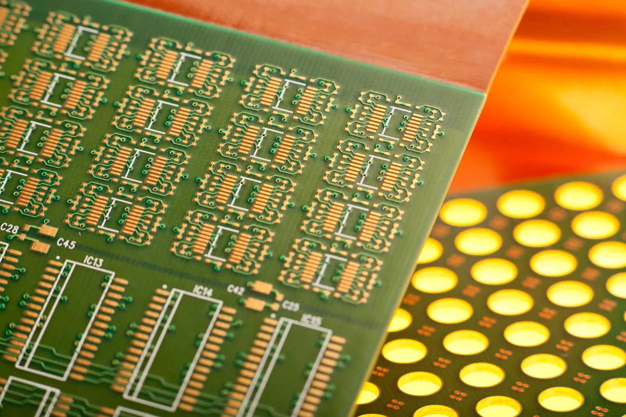
Hybrid boards need both soldering worlds. Through-hole parts are commonly joined by wave soldering, where the assembled board passes over a standing wave of molten solder that fills the plated holes from the bottom, while the surface mount parts on the same board have already been joined by reflow. The order of the two steps, the tooling that protects the reflowed components, and the solder mask design around the through-hole pads are planned together, because a process that is perfect for one technology can damage the other.
People and maintenance decide how long the line stays efficient. Operators must be trained to watch the real signals of the process, from paste printing defects to placement drift, and the equipment needs scheduled inspection and maintenance even when production is busy. A machine failure that stops a high volume line costs far more than the regular downtime that prevents it, which is why disciplined factories protect their maintenance time as carefully as their production time.
Quality Gates Between Soldering and Shipment
Testing in volume production is a chain, not a single checkpoint. After soldering, the board should pass inspection, electrical testing, and functional verification before packing. In-circuit testing finds shorts, opens, and wrong components quickly when the volume justifies the fixture, while flying probes cover low-volume and prototype boards, and functional testing proves that the assembled product behaves as designed in its real application.
Every gate must produce data that the factory can use. Traceability records link each board to the paste batch, the reflow profile, the placement machine, and the operator, so a field failure can be traced back to the exact production conditions. In high volume assembly, the process data is the quality system, and the customer receives boards that were verified at every step rather than only at the end of the line.
How gopcb Runs High Volume PCB Assembly
gopcb builds high volume PCB assembly orders with a documented process for every step. Solder paste is selected for the board finish and stored under controlled conditions, placement programs are balanced across the line, reflow profiles are validated on real product, and inspection data is kept with the batch. When an order repeats, the stored process parameters are reused, so the second batch matches the first.
The full service chain is under one roof: PCB manufacturing for the bare boards, SMT PCB assembly for surface mount production, PCB assembly for mixed SMT and through-hole boards, turnkey PCB assembly for complete orders, and PCBA testing as the final quality gate. Send gopcb your design files and target volume to get a production plan with the right soldering process for your board.