ICT Testing on SMT Lines: Bed-of-Nails In-Circuit Test Explained
What ICT Testing Does on an SMT Line
In-circuit testing, usually shortened to ICT, checks an assembled board for manufacturing defects by testing the electrical behavior of the components while they are still mounted on the board. The board is pressed onto a specially designed fixture, spring-loaded test probes touch the component leads and test pads, and the tester measures each network individually. Because the probes contact essentially every net on the board, ICT can verify analog and digital devices separately and diagnose faulty areas quickly.
ICT belongs to a family of contact detection techniques with strong fault diagnosis ability. Unlike automated optical inspection, which judges the board by its appearance, ICT measures real electrical values, so it catches problems that vision cannot see: a solder bridge hidden under a component, an open via, a wrong resistor value, or a part inserted with reversed polarity. The method has been widely used in electronics manufacturing for decades and remains a standard choice for boards produced in volume.
This article explains how the bed-of-nails tester works, what ICT detects, where it fits in the SMT testing strategy, and when the investment in a fixture makes sense.
How the Bed-of-Nails Fixture Works
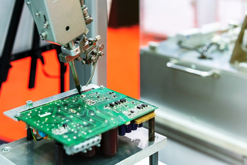
The heart of ICT is the fixture, often called a bed of nails. The fixture holds the printed circuit board in an exact position while dozens or hundreds of spring-loaded probes rise from the base and contact the test points designed into the board. Each probe connects one network to the test system through the fixture wiring, so the tester can apply signals and take measurements at any point on the board without powering the whole product.
Fixture design follows strict rules. Because the fixture is machined on CNC equipment, the test probes must be arranged on a regular grid, normally 2.54 millimeters or 1.27 millimeters, which means the minimum distance between neighboring probes is limited by the grid pitch. Boards tested by ICT therefore need accessible test points laid out at the beginning of the design, and very dense assemblies may not leave room for a full bed of nails.
Fixture cost and development time are real constraints. Creating the fixture, writing the test program, and proving it on real boards takes time, and the price scales with the number of test points and the complexity of the board. These factors make ICT most economical for products with a reasonable assembly density that run in mass production, where the fixture cost is spread over a large quantity of boards.
From MDA to Full ICT Instruments
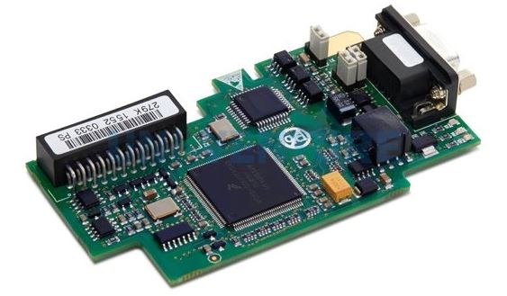
In-circuit test instruments come in two main forms. The manufacturing defect analyzer, or MDA, is the simpler and older type. It performs analog measurements using voltmeters, ammeters, ohmmeters, and similar instruments, and the whole process is controlled by software. An MDA can verify whether components are missing, whether polarity is correct, and whether resistors, capacitors, diodes, and transistors meet their expected values. Because an MDA does not drive the devices, it cannot truly test digital components, but it is fast to program, inexpensive, and quick in response.
A full ICT system is far more powerful than an MDA. In addition to the analog checks, it can exercise digital devices with test vectors and verify their function on the board. ICT can detect almost all defects related to the manufacturing process, from shorts and opens to wrongly loaded parts, which is why it has become the standard for production testing. As electronic products moved into the digital era, the MDA largely left the mainstream testing field, and modern ICT equipment absorbed its role.
Choosing between MDA-style testing and full ICT depends on the product. Simple boards with mostly passive components may be covered adequately by analog checks, while boards with microcontrollers, memories, and complex power circuits justify the higher capability of a full ICT system.
What ICT Detects on Assembled Boards
ICT concentrates on manufacturing faults rather than design faults. The most common findings are solder shorts between adjacent pins, open connections caused by missing solder or lifted leads, missing components, and parts placed in the wrong position or wrong orientation. The tester also measures component values, so a resistor loaded with the wrong value or a capacitor outside tolerance is reported before the board moves to functional testing.
Polarity-sensitive parts receive special attention. Diodes, tantalum capacitors, and other polarized components that were placed backwards show up clearly in the electrical measurements, even when they look correct to an inspector. For digital devices, the test program can apply stimulus patterns and check the response, which verifies that the integrated circuit is present, correctly oriented, and functionally alive.
The power connections of the board are verified as well. The tester checks that every supply rail reaches the components that need it and that there are no low-resistance bridges between rails, protecting downstream functional testing from ambiguous failures. A board that passes ICT arrives at the next test stage with a clean bill of health for the assembly process.

Inside the ICT System: Five Subsystems
A full needle-bed online test system is built from five cooperating parts: the computer control subsystem, the measurement subsystem, the signal excitation subsystem, the switching subsystem, and the test access fixture together with the unit under test. Understanding these blocks helps a production team maintain the tester, write better programs, and judge whether an in-circuit test PCBA station really fits its line.
The computer control subsystem contains the computer hardware, the communication interfaces, the test operating software, the graphical user interface, and the peripheral equipment. It is the brain of the system: it loads the test program, talks to every instrument, stores the results, and presents the operator with a clear pass or fail picture for every board that comes off the line.
The measurement subsystem is the collection of programmable measuring instruments and auxiliary test modules that detect the response of the circuit under test to the excitation signals and compare the readings with the expected values stored in the program. The signal excitation subsystem holds the programmable signal sources, such as power supplies, integrated signal generators, and counters, and during the test it automatically selects the excitation that matches the programming instructions and applies it to the board.
The switching subsystem controls the automatic routing to the selected test channel: it loads the excitation signal, connects the measurement subsystem, and links the test needle bed and its probes to the tester. Modern online test equipment presents all of this through a simple, intuitive graphical interface, usually running on a standard operating system, so an operator can choose the correct test channel for the board under test and watch the excitation and response waveforms live while the program runs.
Where ICT Sits in a Full Testing Strategy
ICT gives the strongest electrical diagnosis of the manufacturing process, but a production line normally combines it with other checks rather than relying on it alone. Solder paste inspection verifies the print before placement, automated optical inspection checks component presence, position, and visible joints after reflow, and X-ray inspection sees hidden joints such as ball grid arrays. Each method covers a different class of defect, and together they give fast feedback at the point where the fault was created.
For prototypes and very small batches, a flying probe tester is often used instead of ICT because it needs no fixture and can be programmed from the netlist quickly. The trade-off is speed: flying probes contact the board one point at a time, so full electrical coverage on high-volume products becomes too slow. When production volume grows and the board design is stable, the fixture investment in ICT is recovered by test times measured in seconds per board and by fault diagnosis precise enough to point at a single defective component.
Choosing the mix depends on the product. Boards that must be extremely reliable, such as medical, automotive, and industrial control electronics, usually justify bed-of-nails coverage in mass production, while simpler consumer boards may rely on optical inspection combined with functional test. Whatever the combination, the board should be designed with accessible test points, clear polarity marks, and testable nets from the start, because testability added after layout is expensive and incomplete.
How gopcb Applies ICT on Its SMT Lines
At gopcb, ICT is one layer of a documented testing plan that also includes solder paste inspection, automated optical inspection, X-ray inspection for hidden joints, and functional testing before shipment. When an order justifies the fixture investment, our engineering team reviews the board for test point coverage, agrees the test list with the customer, and introduces the fixture into production so that every batch is guarded against shorts, opens, missing parts, and wrong components.
The whole service chain sits under one roof: PCB manufacturing for the bare boards, SMT PCB assembly for precise placement, PCBA testing for electrical verification including ICT, and PCB assembly for mixed technology boards, with turnkey PCB assembly available when you want one partner for the entire flow. Send your design files to gopcb to discuss ICT coverage, fixture cost, and the testing strategy for your next batch.