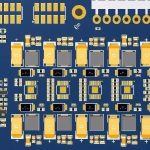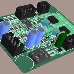
Metal Core PCB technology is widely used in applications where thermal management, structural rigidity, and long-term reliability are important. Unlike conventional FR-4 PCBs, metal core boards incorporate a metal substrate—commonly aluminum or copper—to provide a more effective thermal path for heat generated by electronic components.
Although Metal Core PCB Design follows many fundamental principles used for conventional PCBs, the presence of the metal substrate introduces additional electrical, thermal, mechanical, and manufacturing considerations.
High-power electronics can generate significant heat during operation. If that heat cannot be removed efficiently, excessive junction or board temperature can reduce component lifetime, cause performance degradation, or lead to premature failure. Even relatively low-power electronics may require a metal-backed PCB when they operate continuously in a high-temperature environment.
For this reason, Metal Core PCB technology is commonly considered for LED lighting, power electronics, industrial equipment, automotive systems, renewable energy equipment, and other applications where thermal performance is critical.
What Is a Metal Core PCB?
A Metal Core PCB is a circuit board that uses a conductive metal substrate as part of its construction. Aluminum is widely used because it offers a practical combination of thermal conductivity, weight, cost, and manufacturability. Copper substrates may be selected when substantially higher thermal conductivity is required.
A typical metal core structure may include:
- Copper circuit layer
- Dielectric insulation layer
- Aluminum or copper metal substrate
The dielectric layer electrically isolates the copper circuit from the metal substrate while providing a thermal path from the circuit layer toward the metal core.
This structure allows heat to travel from components through the PCB and into the metal substrate, where it can be distributed or transferred to a heat sink, chassis, or other thermal structure.
Therefore, the main advantage of a metal core board is not simply that it contains metal. Its value comes from providing a controlled thermal path within the PCB structure.
Applications of Metal Core PCBs
Metal Core PCB technology can be used in many applications where conventional FR-4 construction may not provide sufficient thermal performance or mechanical characteristics.
LED Lighting
High-power LED modules are one of the most common applications for metal-backed circuit boards.
LEDs convert electrical energy into light and heat. Efficiently removing this heat is essential for maintaining LED performance and service life.
A metal core board can transfer heat away from the LED package through the copper layer and dielectric into the metal substrate.
Typical applications include:
- High-power LED lighting
- Street lighting
- Industrial lighting
- Automotive lighting
- Architectural lighting
- Display backlighting
Power Conversion and Power Management
Power electronic circuits often contain components that generate substantial heat, including MOSFETs, IGBTs, power diodes, inductors, and switching regulators.
Metal Core PCB Design may be appropriate for:
- Power supplies
- DC-DC converters
- Motor drives
- Industrial power systems
- Battery management systems
- Automotive power electronics
- Telecommunications power equipment
The thermal design must consider not only the PCB material but also component placement, copper distribution, interface materials, and the final heat-dissipation structure.
Renewable Energy Equipment
Solar power electronics, battery systems, and other renewable-energy equipment can operate under demanding electrical and environmental conditions.
Depending on the system architecture, a Metal Core PCB can help improve thermal performance and mechanical stability in power conversion and control assemblies.
The final board construction should be selected according to voltage, current, operating temperature, insulation requirements, and expected lifetime.
Automotive Electronics
Automotive electronic systems often experience elevated temperatures, vibration, limited installation space, and continuous operation.
Metal core construction may be considered for applications such as:
- LED lighting
- Power modules
- Motor control
- Battery-related electronics
- Thermal management modules
However, automotive applications require careful consideration of vibration, thermal cycling, insulation, corrosion resistance, and qualification requirements.
Industrial and Aerospace Electronics
Industrial control systems and aerospace-related electronics may require high reliability under demanding operating conditions.
A metal substrate can provide both thermal spreading and structural support. However, aerospace applications may impose additional requirements related to weight, thermal cycling, materials, flammability, outgassing, reliability, and qualification.
The PCB structure should therefore be selected based on the complete system requirements rather than thermal conductivity alone.
Metal Core PCB Stackup
The stackup of a metal core board differs from a conventional multilayer FR-4 PCB.
A basic metal core structure commonly consists of:
Copper Circuit Layer → Dielectric Layer → Metal Core
The copper layer carries electrical signals and power, while the dielectric provides electrical isolation and transfers heat toward the metal substrate.
Some specialized structures can incorporate additional dielectric and copper layers. However, the feasible stackup depends heavily on the manufacturer’s process capabilities and the required electrical and thermal performance.
Therefore, multilayer Metal Core PCB Design should be discussed with the PCB manufacturer before finalizing the stackup.
Thermal Management in Metal Core PCB Design
Thermal management is one of the most important considerations when designing a metal core board.
The complete thermal path can be viewed as:
Component → Copper Pattern → Dielectric → Metal Core → Thermal Interface → Heat Sink or Chassis
Every part of this path contributes thermal resistance.
A highly conductive metal core does not automatically guarantee low operating temperature. If the dielectric is too thick, the component-to-copper connection is inefficient, or the interface between the PCB and heat sink is poor, the overall thermal performance can still be limited.
Important design factors include:
- Dielectric thermal conductivity
- Dielectric thickness
- Copper thickness
- Copper area
- Component power dissipation
- Component placement
- Metal core material
- Thermal interface material
- Heat sink design
- Ambient temperature
- Airflow and enclosure conditions
For high-power applications, thermal simulation or measurement can be useful for validating the design before production.
Metal Core PCB Grounding
The metal substrate should not automatically be treated as an electrical ground plane.
Depending on the board construction, the metal core may be electrically isolated from the circuit layers by the dielectric. Whether it is connected to chassis ground, protective earth, circuit ground, or left electrically isolated depends on the system architecture and safety requirements.
In some applications, connecting the metal substrate to an appropriate reference or chassis structure can contribute to EMI control or provide a low-impedance thermal/mechanical interface.
However, designers should avoid assuming that the metal core can simply replace a conventional PCB ground plane.
For high-speed or RF applications, grounding must be evaluated together with:
- Return-current paths
- Reference planes
- Controlled impedance
- Layer transitions
- Shielding structures
- Chassis connections
- Common-mode current paths
The correct grounding strategy is therefore application-dependent.
Single-Sided Metal Core PCB
Single-sided metal core boards are relatively straightforward to manufacture and are widely used in thermal applications.
A typical structure places the copper circuit layer and components on one side while leaving the metal substrate exposed on the opposite side.
The exposed metal surface can then be connected to:
- A heat sink
- Metal chassis
- Thermal mounting plate
- Mechanical housing
This structure can provide a relatively short thermal path from the component to the external heat-dissipation system.
When the metal substrate is electrically isolated, the interface between the PCB and heat sink must also be evaluated to ensure that the required electrical insulation is maintained.
Double-Sided Metal Core PCB
Double-sided Metal Core PCB construction is more complicated because electrical connections may be required between the two circuit sides while the metal substrate is located between or beneath the circuit structures.
The feasibility of through-holes and vias depends strongly on the specific stackup and manufacturing process.
Designers should therefore not assume that standard FR-4 through-hole processing can be directly transferred to every metal core structure.
Special considerations may include:
- Electrical isolation around drilled holes
- Via-to-metal clearance
- Dielectric integrity
- Hole-wall reliability
- Plating requirements
- Thermal expansion
- Mechanical stress
- Manufacturing sequence
Early DFM communication with the manufacturer is particularly important for complex metal core constructions.
Vias and Hole Design
Via design requires special attention when the metal substrate is located close to the copper circuitry.
For conventional PCBs, a plated through-hole can pass through insulating dielectric and connect different copper layers. In a metal core structure, however, the metal substrate may create a potential electrical short if the hole passes through it without appropriate isolation.
Depending on the construction, manufacturers may use specialized drilling, insulation, routing, or dielectric structures to maintain electrical separation.
Therefore, via design should consider:
- Finished hole diameter
- Drill diameter
- Pad diameter
- Clearance to the metal core
- Plating thickness
- Board thickness
- Aspect ratio
- Thermal cycling
- Electrical isolation requirements
The exact manufacturing solution should be determined according to the selected stackup rather than applying one universal hole-processing method.
Thermal Vias
Where the board structure allows them, Thermal Vias can improve heat transfer from component pads into an underlying copper region or thermal structure.
They are particularly useful for components such as:
- Power ICs
- MOSFETs
- Power diodes
- LED packages
- Thermal pads
However, thermal vias are not universally required on every metal core board. Their effectiveness depends on the actual stackup and thermal path.
Designers should evaluate via diameter, pitch, number, pad geometry, plating, and manufacturing capability during the design stage.
PCB Layout Considerations
Good PCB Layout remains essential even when a metal substrate is used.
The following practices can improve thermal and electrical performance:
Place High-Power Components Strategically
Heat-generating components should be positioned where their heat can be efficiently transferred into the metal substrate and ultimately to the external cooling structure.
Avoid concentrating multiple high-power devices in a small area unless the thermal design has been specifically engineered for it.
Use Adequate Copper Area
Large copper areas can reduce electrical resistance and help spread heat across the circuit layer.
Copper thickness should be selected according to current requirements, thermal performance, manufacturing capability, and cost.
Keep High-Current Paths Short
High-current paths should be designed with appropriate copper width and thickness.
Reducing unnecessary path length can lower resistance and power loss:
P = I²R
For switching power circuits, minimizing high di/dt loop area can also help reduce parasitic inductance and electromagnetic noise.
Separate Sensitive and Noisy Circuits
If the board contains both power switching and sensitive analog or communication circuits, the layout should control coupling between noisy and sensitive sections.
This may require careful placement, grounding, routing, filtering, and return-current management.
DFM for Metal Core PCB
PCB DFM is particularly important for metal core boards because their manufacturing process can differ substantially from standard FR-4 fabrication.
Before production, designers and manufacturers should review:
- Board thickness
- Copper thickness
- Dielectric thickness
- Dielectric thermal conductivity
- Metal substrate type
- Minimum trace width and spacing
- Pad geometry
- Drill and via structures
- Metal-core clearance
- Board outline
- Edge treatment
- Surface finish
- Solder mask
- Component assembly requirements
The goal of PCB DFM is to ensure that the design can be manufactured consistently rather than simply verifying whether the CAD software accepts the geometry.
Electrical Clearance and Insulation
Metal core boards require particular attention to electrical isolation because the metal substrate is conductive.
Designers should evaluate:
- Copper-to-metal-core clearance
- Hole-to-metal-core clearance
- Pad-to-metal-core clearance
- Creepage
- Clearance
- Dielectric breakdown requirements
- Working voltage
- Pollution degree
- Operating environment
Applicable safety requirements should be determined according to the product category and relevant standards.
Rather than applying a single clearance value to every project, the designer should establish the required spacing from the applicable electrical safety requirements and manufacturing capability.
Mechanical Design Considerations
The metal substrate also affects the mechanical behavior of the PCB.
Designers should consider:
- Board weight
- Thermal expansion
- Mounting method
- Screw-hole locations
- Enclosure interfaces
- Heat sink attachment
- Flatness
- Mechanical stress
- Thermal cycling
Differences in the coefficient of thermal expansion between the metal substrate, dielectric, copper, and mounted components can introduce mechanical stress during temperature changes.
This becomes increasingly important in applications that experience frequent thermal cycling.
Manufacturing and Assembly Considerations
Metal Core PCB Manufacturing requires coordination between PCB fabrication and assembly processes.
During assembly, designers should consider:
- Component footprint design
- Solder mask configuration
- Stencil design
- Reflow profile
- Board thermal mass
- Component temperature limits
- Solderability
- Fixture requirements
Because the metal substrate can change how heat is distributed during soldering, the reflow process may behave differently from a conventional FR-4 board.
The assembly process should therefore be validated using the actual board construction rather than assuming that an existing FR-4 profile will always be appropriate.
Metal Core PCB vs. Conventional FR-4 PCB
The choice between a metal core board and conventional FR-4 should be based on system requirements.
| Factor | Metal Core PCB | Conventional FR-4 PCB |
|---|---|---|
| Thermal spreading | Generally strong | Depends strongly on construction |
| Structural rigidity | High | Moderate to high |
| Weight | Application-dependent | Generally lower |
| Cost | Often higher | Broad range |
| High-power applications | Well suited | May require additional thermal solutions |
| Multilayer flexibility | More process-dependent | Highly established |
| Electrical isolation | Requires careful dielectric design | Naturally provided by dielectric layers |
| Heat-sink integration | Convenient in many designs | Often requires additional structures |
A metal core board is not automatically better than FR-4. It is most valuable when the thermal and mechanical advantages justify the additional material and manufacturing considerations.
How Kingda Supports Metal Core PCB Manufacturing
Successful Metal Core PCB Manufacturing begins with a design that considers fabrication requirements from the beginning.
Kingda can support design-for-manufacturing discussions covering material selection, copper thickness, dielectric structure, board dimensions, thermal requirements, via structures, electrical isolation, and assembly considerations.
For high-power and thermally demanding applications, early collaboration between the design team and PCB manufacturer can help identify potential manufacturing risks before production.
This approach is especially useful when the project requires customized metal core structures, high copper thickness, complex thermal paths, or special electrical isolation requirements.
Conclusion
Metal Core PCB technology provides an effective solution for electronic products that require improved thermal management, structural support, and reliable operation under demanding conditions.
However, successful Metal Core PCB Design requires more than simply replacing an FR-4 substrate with a metal substrate.
Engineers must evaluate the complete electrical and thermal structure, including dielectric properties, copper thickness, component placement, grounding, vias, insulation, mechanical expansion, assembly, and heat-sink integration.
At the same time, PCB DFM should be incorporated early in the design process to ensure that the selected structure can be manufactured consistently and economically.
By combining proper thermal design, electrical isolation, mechanical engineering, and manufacturer collaboration, a metal core PCB can provide a reliable foundation for high-power LED systems, power electronics, automotive applications, industrial equipment, renewable-energy systems, and other demanding electronic products.