Dog Bone vs Via-in-Pad PCB: Which BGA Fan-Out Design Is Better?
What Are Dog Bone and Via-in-Pad Fan-Out?
Every PCB that carries a fine-pitch BGA package faces the same question at the layout stage: how do we break the hundreds of solder balls out to the inner layers and the rest of the board? The two mainstream answers used across the industry are the dog bone fan-out and the via-in-pad fan-out, sometimes called VIPPO. Both connect each BGA pad to a via and then to the internal routing layers, but they place the via in different positions and go through very different PCB manufacturing processes.
Dog bone routing keeps the via next to the pad and joins them with a short trace, while via-in-pad drilling places the via directly inside the pad itself. That single geometric difference drives everything downstream: board size, layer count, routing density, signal quality, thermal behavior, production yield and unit cost. Engineers working on AI servers, 5G infrastructure, automotive electronics and consumer products all need to pick the right approach early, because changing fan-out strategy after the stack-up is fixed is expensive.
This guide compares dog bone and via-in-pad construction from design, fabrication, cost, signal integrity and reliability angles, and gives a practical decision path for choosing between them.
How Dog Bone Fan-Out Works
Dog bone is the classic and still the most widely used BGA fan-out. As the name suggests, the footprint looks like a dog bone: a short copper trace leaves the BGA pad and ends at a via positioned outside the pad area. The typical structure contains the BGA pad, a very short connecting trace, and a through-hole or microvia placed one pad away.
Because the via is drilled outside the pad, the board keeps conventional drilling and plating steps. There is no hole sitting under the solder ball, so the pad surface stays solid for the solder joint, and standard SMT assembly can be used without special plugging. Dog bone fan-out remains the mainstream choice for BGA packages with 0.8 mm pitch and above, and it is the option that the majority of PCB factories can manufacture without extra process equipment.

What Is Via-in-Pad or VIPPO?
Via-in-pad places the via hole directly inside the component pad, and VIPPO (Via in Pad Plated Over) is the finished form used for assembly. If a plain hole were left in the pad, molten solder would wick down the barrel during reflow and starve the joint, so a set of special process steps is required: the via is filled, usually with resin, optionally plated with copper for thermal or high-current reasons, the surface is planarized so the pad is flat again, and the pad is re-plated and finished with ENIG or another surface finish.
Once completed, a VIPPO pad is flat and fully solderable, and the via effectively disappears from the assembly surface. The approach is indispensable on high-density boards and on pads that are simply too small to route a dog bone trace between neighboring balls, which is typical of 0.65 mm pitch and finer BGAs.
Advantages of Dog Bone Routing
Dog bone construction wins on cost, maturity and speed of manufacture. Because no via filling, copper plating or planarization is needed, the fabrication flow is identical to a normal multilayer board. That simplicity translates directly into a lower price per board, higher yields, fewer defects and shorter lead times, typically twenty to forty percent faster than an equivalent via-in-pad design.
Inspection and rework are also easier. With vias outside the pads, automated optical inspection sees clean pad geometry, ICT fixtures can probe conventionally, and a failed joint can be reworked without fighting a buried hole under the pad. For cost-sensitive products in consumer electronics and industrial control, and for most designs above 0.8 mm pitch, dog bone routing remains the economical default that is difficult to beat.
Advantages of Via-in-Pad Construction
Via-in-pad exists for one reason: it removes the escape trace and therefore frees routing space. The via consumes no pad-to-pad corridor, which opens additional routing channels, raises wiring efficiency, shrinks the board footprint and lets designers pack more functionality into the same area. This is why VIPPO is one of the enablers of HDI PCB design and of miniaturized products with very dense BGAs.
Electrical performance improves as well. The signal path from the ball to the via is shorter, which lowers parasitic inductance and capacitance, improves impedance continuity, reduces reflections and lowers crosstalk. Those benefits matter for DDR5 memory, PCIe Gen 5 and Gen 6, USB4, 112G SerDes links, AI accelerators and high-end switches where every fraction of a millimeter of stub affects the eye diagram.
Thermally, a filled via under a power pad creates a direct copper path to the internal planes and can move heat away from the package quickly. Processors, GPUs and power devices use arrays of via-in-pad holes precisely for this thermal function even when signal routing does not demand it.
Manufacturing and DFM Differences
The fabrication gap between the two options is wider than most buyers expect. Dog bone boards run through standard drill, plate and solder mask operations with well-understood yields. Via-in-pad boards add resin plugging, optional copper filling, surface planarization and re-plating, and each extra step brings registration, cleanliness and flatness requirements that must be controlled tightly.
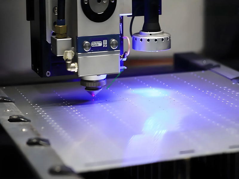
For reliable results, via-in-pad holes are usually laser-drilled microvias in the 0.1 to 0.2 mm range that can be filled cleanly, and the design should specify the fill type, the plating thickness and the surface finish. A good DFM review checks via size against pad size, fill coverage, annular ring and stack-up compatibility before the files go to production. Designers should also remember that via-in-pad is not a switch you can flip late in the process: the stack-up, drill method and finish all need to be planned from the first layout pass.
Cost Comparison in 2026
In 2026 pricing, dog bone routing is clearly the cheaper process. The standard flow avoids plugged-via surcharges, copper fill costs and extra grinding and plating operations, so dog bone boards generally cost less to fabricate and can be twenty to forty percent faster to deliver. The premium for via-in-pad depends on the number of vias, the hole size and the fill type: resin-filled and plated-over vias on a dense HDI stack carry a noticeable per-panel uplift, and copper-filled vias for thermal pads cost more again.
That premium is usually justified only where density or performance demands it. On boards with spare routing space and standard pitch, paying for via-in-pad adds cost without adding value. On a high pin count module where the alternative is an extra layer pair or a larger board, via-in-pad often turns out to be the cheaper overall solution once total board cost is compared, which is why the decision should always be made against the complete stack-up and panel cost, not against a single per-via price.
Signal Integrity and Thermal Behavior
Signal integrity favors via-in-pad in dense, high-speed sections because the connection is shorter and the return path is tighter. Dog bone traces add a small amount of inductance and capacitance at every ball, and at very high data rates those parasitics accumulate across hundreds of differential pairs. For moderate speeds, however, dog bone routing with well-controlled trace geometry performs perfectly well, and few designs below 10 Gbps will ever notice the difference.
Thermally, the filled copper via-in-pad is the stronger solution for hot packages because it sinks heat straight into the planes. Dog bone boards still dissipate heat effectively through normal thermal vias placed beside the pads, and most non-power BGA devices run cool enough that the difference is irrelevant. Choose the thermal strategy from the actual power dissipation of the component rather than from fashion.
How to Choose Between Dog Bone and Via in Pad
Start with pitch. For BGA pitch of 0.8 mm or more, dog bone routing is normally the right choice: it is cheaper, faster, easier to inspect and fully capable of the required density. For pitch of 0.65 mm or below, via-in-pad is usually necessary because there is no room for an escape trace between balls.
Then consider the product requirements. High-speed interfaces, aggressive miniaturization, high pin count modules and power-hungry packages push toward via-in-pad, while cost-sensitive, moderate-density and standard-speed designs stay with dog bone. When the stack-up is still flexible, ask the manufacturer to quote both options on the same design: the comparison of layer count, panel utilization, assembly cost and lead time will usually make the decision obvious.
FAQ
Is via-in-pad always better than dog bone? No. Via-in-pad is better for dense, high-speed or thermally demanding designs, but it costs more and takes longer to build. For standard pitch boards, dog bone routing is the better value.
What pitch requires via-in-pad? As a rule of thumb, 0.65 mm pitch and below generally needs via-in-pad, while 0.8 mm pitch and above can normally use dog bone fan-out.
Can a dog bone design be changed to via-in-pad later? Technically yes, but the stack-up, drilling plan and finishes are different, so the change is easier before the design is released to fabrication. Early DFM feedback saves both time and money.
Validate the Fan-Out With Your Manufacturer
Whatever route you choose, the fastest way to avoid surprises is to review the fan-out plan with the factory before release. A capable partner will check via sizes, fill requirements, pad geometry and stack-up compatibility, and will tell you honestly whether dog bone routing can save you money or whether the pitch forces via-in-pad.
gopcb offers multilayer PCB manufacturing with standard dog bone processing as well as resin-filled and copper-filled via-in-pad capability, plus PCB assembly and testing services under one roof. Send your BGA design files for a free DFM review and receive a clear recommendation on fan-out strategy with a quotation that reflects the real process.