High Voltage PCB Material: Selection Guide for 2026
Why Material Choice Defines a High Voltage PCB
A high voltage PCB works in circuits that carry 300, 600, 1000 volts or more, from electric vehicle power trains and energy storage to industrial power supplies, rail systems and medical equipment. At those voltages the laminate is no longer a passive carrier; it is the primary insulation barrier between conductors, and its properties decide whether the product is safe for its whole life or fails prematurely in the field.
Ordinary boards running below 48 volts tolerate mediocre insulation performance, but high voltage systems face electrical breakdown, leakage current, arcing, corona discharge, insulation aging, thermal failure and surface tracking in humid conditions. Even a well laid out board can fail early if the base material was chosen poorly. That is why the selection of the high voltage PCB material is the first and most important design decision.
This guide explains the properties that matter, compares the main material families, maps them to applications and gives practical design and cost guidance.
Key Properties to Evaluate
Seven properties separate a genuine high voltage material from an ordinary one. Dielectric strength measures how much electric field the material can survive before breakdown, and high values are essential above 1000 volts. CTI, the comparative tracking index, rates resistance to tracking under contamination and moisture; CTI above 600 is excellent, 400 to 600 is good, and below 250 is poor for high voltage work.
Dielectric constant and dissipation factor matter where high frequency and high voltage meet, such as radar, RF power supplies and medical systems, because low loss materials improve efficiency and signal quality. Glass transition temperature sets the safe operating temperature: at least 170 degrees Celsius for industrial products, 180 to 200 for automotive and inverters, and above 200 for aerospace. Thermal conductivity controls how heat escapes, and low moisture absorption keeps insulation resistance high because absorbed water collapses dielectric performance.
Material selection also needs to consider how the board will be assembled and coated. High voltage boards often carry large components, tall creepage barriers and conformal coating or potting, and the laminate must survive multiple soldering passes without losing its insulation properties. Cleanliness after assembly matters as much as the base material, because flux and ionic residue create the exact leakage paths that high voltage design tries to eliminate. Suppliers that combine material knowledge with disciplined assembly and post-processing control give high voltage products the safety margin they need.
Main Material Families Compared
High Tg FR-4 remains the most widely used high voltage material. It is inexpensive, mature and mechanically strong with good insulation, and it comfortably serves 300 to 1000 volt applications such as industrial power, UPS, PLC, motor drives and general control equipment. For most commercial high voltage products, high Tg FR-4 with the right clearance rules is the sensible default.
Ceramic PCBs deliver the highest insulation and heat spreading capability, with outstanding dielectric strength, thermal conductivity and dimensional stability. They are the material of choice for IGBT modules, EV controllers, medical and laser equipment and high power LED products where both voltage and heat are extreme. PTFE and other low loss high frequency laminates combine high voltage capability with very low dielectric loss for radar, satellite communication, microwave systems and high frequency power supplies, while polyimide serves aerospace, defense and flexible high voltage circuits with its high temperature resistance and stable electrical properties.
Metal base IMS boards add a thermal core, giving excellent heat spreading and power handling for LED drivers, industrial power and large inverters, with slightly lower dielectric performance than ceramic. Each family wins in its own application window, which is why the correct answer is always application specific.
Matching Material to Application
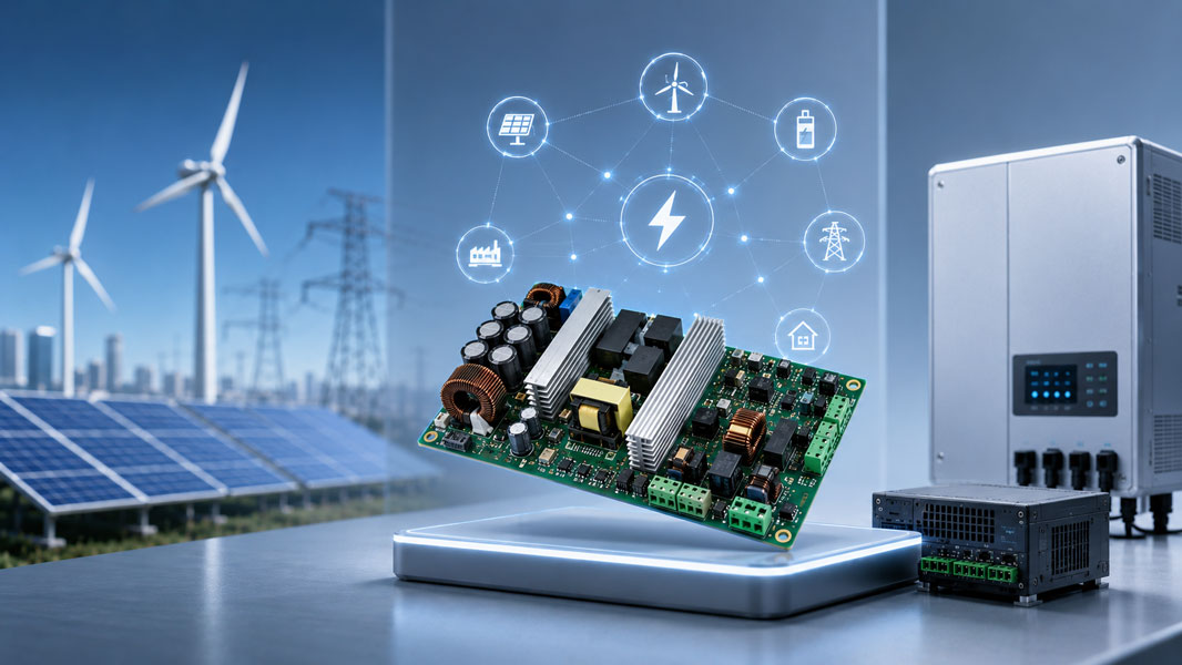
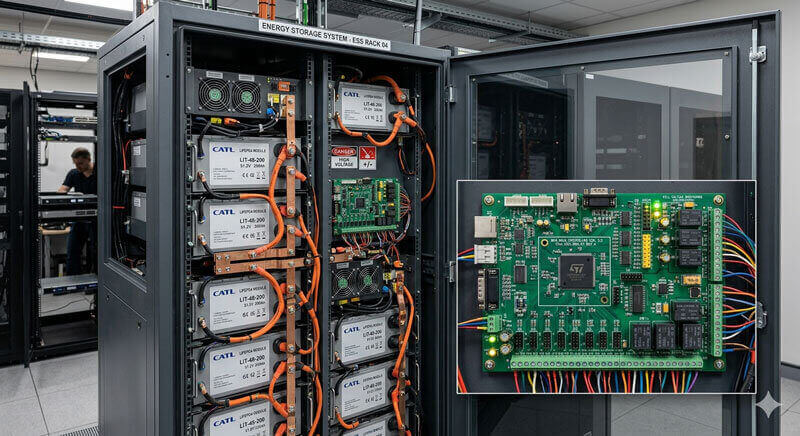
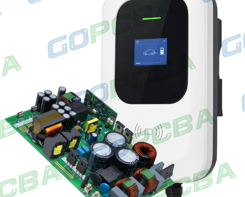
Electric vehicles and their chargers use ceramic, high Tg FR-4 and IMS boards across the battery management system, on-board charger, DC-DC converters and drive controllers. Solar inverters and storage systems pair high Tg FR-4 with ceramic where switching devices run hot under continuous high voltage. Medical imaging and laser systems choose ceramic or polyimide for insulation and reliability.
Industrial power supplies balance cost and performance with high Tg FR-4 and thick copper, while high frequency high voltage systems specify PTFE or Rogers laminates. Defining the application envelope, the voltage class, the temperature range and the reliability target before material selection keeps the choice honest and economical.
IPC Standards That Apply
High voltage design and manufacturing sit inside a clear standard framework. IPC-2221 provides general design rules including clearance and creepage guidance, IPC-6012 covers rigid board performance, IPC-A-600 defines acceptance criteria and IPC-A-610 covers assembly quality. Power conversion products also reference IPC-9592, which sets design requirements for power conversion equipment. Following these standards protects insulation reliability and keeps the product safe across suppliers.
Design Rules That Complete the Material
Material alone is not enough; the layout must respect the physics of high voltage. Creepage and clearance distances must scale with working voltage, and high CTI materials allow shorter creepage while preserving reliability. Copper traces should use rounded corners and chamfers instead of sharp angles that concentrate electric fields, and slots can be added between high voltage areas to lengthen the creepage path physically.
Conformal coating or potting adds environmental protection where humidity is a risk, balanced copper and appropriate thickness limit warpage and thermal stress, and cleanliness control during assembly prevents flux residue from turning into a leakage path. A DFM review against these rules raises first pass yield and removes the field failures that trace back to layout oversights.
2026 Price Reference
High voltage material pricing varies with the laminate family and the build. High Tg FR-4 boards follow standard multilayer pricing and are the economical baseline for most 300 to 1000 volt products. Ceramic, PTFE and metal base constructions carry higher material cost, and thick copper or special insulation structures add process cost on top. Prototype quantities of two to six layer high voltage boards typically quote from a few tens to a few hundred US dollars, while volume pricing drops with panel utilization and layer count exactly as it does for conventional boards.
The right way to control cost is to specify the voltage class and environment precisely, choose the least exotic material that passes the insulation and thermal budget, and confirm the creepage and clearance design before quoting.
FAQ
What is the most common high voltage PCB material? High Tg FR-4 is the default for most 300 to 1000 volt products because it balances insulation, cost and manufacturability.
Which material is best for very high insulation and heat? Ceramic PCB material offers the highest dielectric strength and thermal conductivity and is preferred for IGBT, EV and high power medical modules.
Does CTI really matter for high voltage boards? Yes. CTI determines tracking resistance under moisture and contamination, and higher CTI allows safer, more compact creepage design for power and industrial products.
Can standard FR-4 be used at high voltage? Only when the working voltage is modest and the design follows proper creepage, clearance and CTI guidance; above roughly 1000 volts or in humid environments, dedicated materials are the safer choice.
Manufacturing High Voltage Boards Correctly
High voltage PCBs reward manufacturers with real material and process depth. Look for capability with high Tg FR-4, ceramic, PTFE, Rogers, polyimide and IMS materials, thick copper up to 20 ounces, insulation slots and special isolation structures, laser drilling and HDI where needed, and IPC Class 2 or Class 3 production with AOI, flying probe, X-ray and electrical test. gopcb manufactures high voltage and power electronics PCBs for EV, energy storage, industrial and medical customers, with DFM engineering support and prototype through production volumes. Send your stack-up, voltage class and clearance rules for a free DFM review and a quotation matched to the real material requirement.