High-Speed PCB Quality Control Standards: A Complete Guide
Why High-Speed Boards Need Their Own Controls
A conventional digital board tolerates a wide spread in geometry because the signal settles long before the next clock edge. A high speed board does not. A ten percent change in trace width, a 25 micrometre shift in dielectric thickness or a small variation in copper roughness all change the characteristic impedance, and the reflection that follows shows up directly as jitter and eye closure. Quality control on these boards is therefore not only about opens and shorts; it is about holding the electrical parameters that the design assumed inside a narrow band, and proving it with measurements rather than with visual inspection alone.
The Standards That Apply
The baseline is the IPC-6012 qualification and performance specification for rigid boards, with the acceptance criteria class chosen by the end product. Class 2 suits most commercial electronics, Class 3 is required for high reliability applications such as aerospace and medical, and the class changes the allowable annular ring, the hole wall copper, the void limits and the inspection sample size. For high frequency work IPC-6018 covers high frequency and microwave boards and adds requirements for dielectric properties and surface finish. The fabricator’s own process specification sits under both, and the key is that the drawing should state the class, the impedance targets and the test method, because a purchase order that only says IPC-6012 leaves the electrical side undefined.
Impedance Control and Test Coupons
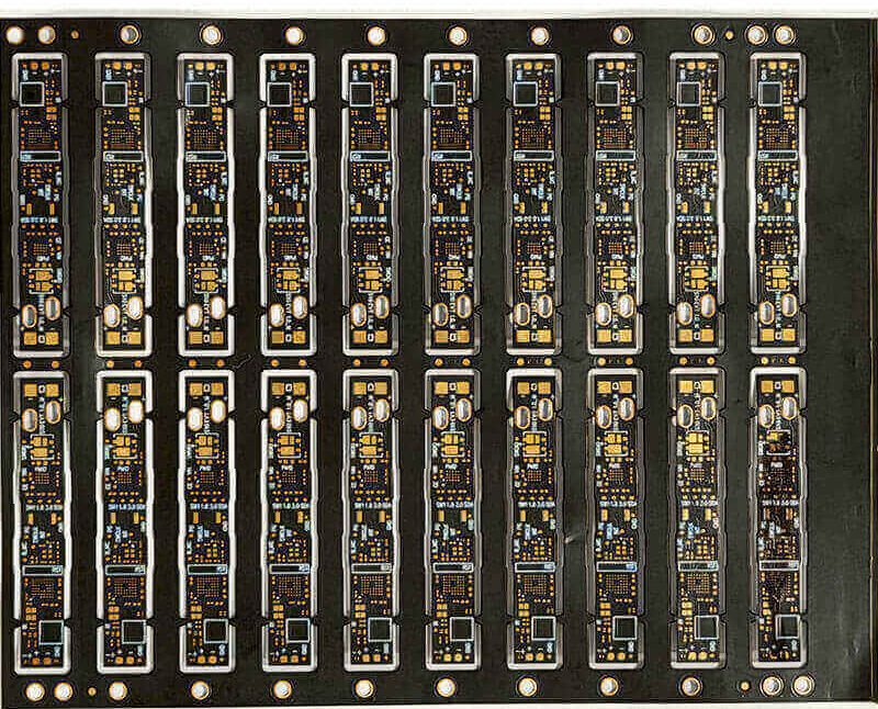
Impedance is the parameter that separates a high speed build from a standard one, and it can only be controlled through the stackup. The fabricator models the geometry from the supplied stackup, then adjusts trace width and dielectric thickness to hit the target, typically within plus or minus ten percent for single ended lines and tighter for differential pairs where the coupling also matters. Verification is done on a test coupon built on the same panel, using a time domain reflectometer, because measuring the finished product directly is impractical. A supplier that cannot supply coupon data for the specific panel is not really offering impedance control.
Material and Copper Controls
The dielectric constant of the laminate is not a single number; it varies with the resin content, the glass style and the frequency. Good control starts with a material specification that names the grade, the dielectric constant and the loss tangent at the frequency of interest, and it continues with incoming inspection of the laminate and prepreg. Copper foil roughness matters because at high frequency the current crowds into the surface and the roughness adds conductor loss, so the foil type should be specified rather than left to the shop. Thickness control on the dielectric layers is the next lever, and it is normally verified by cross section on a coupon from the same panel.
Inspection Methods and Their Limits
Automated optical inspection. Finds missing copper, shorts and pattern defects, but cannot see inside a hole. Automated X-ray inspection. Sees the inner layer registration and the barrel voiding, and is essential for BGA work. Flying probe and bed of nails. Prove electrical continuity and isolation but say nothing about impedance. Cross sectioning. The definitive check on hole copper, dielectric thickness and plating quality, but it destroys the coupon. TDR measurement. The only direct evidence that the impedance target was met. Microsection plus scanning electron microscopy. Used for failure analysis and for qualifying a new process. A credible quality plan uses several of these, because each one is blind to something the others catch.

Process Control Through the Line
Acceptance criteria only catch what is already wrong; process control is what keeps the line from drifting. The critical parameters on a high speed board are the lamination press profile, because it sets the dielectric thickness and the resin flow, the drilling parameters on high frequency laminates, because they smear easily and need plasma desmear, and the plating current density, because it sets the copper distribution in the hole. Each of these should have a monitored set point and a reaction plan. Statistical process control on the impedance coupon result, plotted run to run, is the most practical single indicator that the board is behaving.
What to Write in the Fabrication Drawing
Specify the applicable IPC class and the end product class. Give the stackup with the dielectric constant for each layer at the frequency of interest. State the impedance targets and tolerances, the coupon location and the test method. Name the surface finish and its thickness range. Note any requirement for cross sectioning or microsection on the first article. Require a certificate of conformance with the coupon data, and set an acceptance rule for what happens if the impedance is outside tolerance. Handled that way, the drawing becomes the quality agreement, and the dispute about whether a board conforms is settled by data rather than by opinion.
High speed quality is a joint responsibility between design and fabrication. Review the process capability in PCB manufacturing, apply the impedance and routing rules from PCB design and layout, and read the design and manufacturing considerations before release. A prototype PCB assembly run with a measured coupon set confirms the board meets the target before volume.
FAQ
What tolerance is normal for controlled impedance? Plus or minus ten percent for single ended lines is a common commercial target, with tighter values available on request for differential pairs.
Can impedance be measured on the finished board? Not practically. It is verified on a coupon built on the same panel with a time domain reflectometer.
Which IPC standard covers high frequency boards? IPC-6018 covers high frequency and microwave boards and adds dielectric and finish requirements on top of the rigid board specification.
Is visual inspection enough? No. Optical inspection cannot see hole quality or impedance, so cross sectioning and coupon measurement are required as well.
Conclusion
Quality control on a high speed board means holding dielectric thickness, copper roughness and trace geometry inside a narrow band, then proving it with coupon impedance data and cross sections. Write the class, the stackup and the tolerance into the drawing, insist on a certificate with the coupon results, and monitor the process rather than only the finished panel. Done properly in 2026, the board arrives with evidence that it will meet the eye diagram, not just a promise.