PTFE Laminates: Processing and Design
Why PTFE Is Used
PTFE-based laminates are chosen for their electrical properties: a low and stable dielectric constant and a very low loss tangent, which keeps insertion loss down at high frequency. They are also used where the dielectric constant has to be predictable across a panel, which matters for phase-critical circuits such as filters and phased arrays. The material is not a drop-in replacement for FR4 in the fabrication process: it behaves differently at every step, and the difference shows in the yield and in the achievable features.
Mechanical Behaviour
PTFE is much softer than an epoxy laminate and it is more prone to cold flow under pressure, which affects handling, drilling and lamination. It also has a much higher coefficient of thermal expansion, particularly in the Z direction, so a plated hole in a PTFE board sees more strain during thermal cycling than one in FR4. These properties are what drive the process differences: the material has to be treated more gently, supported more carefully and drilled with different parameters.
Drilling and Hole Preparation
Drilling PTFE requires sharp tools, conservative feed and speed, and often a different entry and exit material, because the resin smears rather than cuts and a blunt tool produces a rough, resin-rich wall that plating cannot bond to. The smear has to be removed, and the treatment has to be aggressive enough for the wall to accept the plating without damaging the soft material. The hole wall quality is the single largest determinant of via reliability in a PTFE board, which is why drilling is where a fabricator’s experience with the material shows most clearly.
Plating and Adhesion
Copper does not bond readily to PTFE, so every surface that will be plated has to be treated. The treatments are chemical, using sodium naphthalenide or a plasma, and they alter the surface so that it becomes wettable and mechanically keyable. The result is effective but sensitive to the process: a treatment that is too weak leaves an unbondable surface, and one that is too strong damages the dielectric. Because the treatment affects the surface only, handling between the treatment and the plating has to be controlled, and the plating chemistry has to be compatible with the material. Where the design also uses a mixed stack, the treatment has to be applied selectively.
Lamination
PTFE laminates generally need higher lamination temperatures and longer cycles than FR4, and the bonding films are different. The material flows differently under pressure, and the amount of flow has to be controlled to avoid the dielectric thickness varying across the panel, which would change the impedance. Because the thickness variation directly affects the electrical performance, a PTFE build is usually specified with a tighter dielectric thickness tolerance than an FR4 build, and the fabricator has to control the lamination cycle accordingly.
Dimensional Stability
PTFE has a larger coefficient of expansion and a lower stiffness than FR4, so a panel moves more during processing and the registration is harder to hold. The movement affects the hole position relative to the pad, which means the annular ring has to allow for a larger tolerance, and it affects the position of the pattern relative to the board edge, which matters for a card edge or a connector. Compensating for the movement in the artwork is part of the fabricator’s process, and a design that is tight on registration should be discussed with the shop rather than assumed to be achievable.
Design Rules
Keep the pad and the ring generous relative to an FR4 design, since more movement has to be absorbed. Specify the dielectric thickness and its tolerance explicitly, since the impedance depends on it. Where the design mixes PTFE and FR4 layers, keep the microwave layer separate and plan the transition rather than running a critical line across the material boundary. Keep the via count low and avoid stacking vias, because the Z expansion of the material stresses the barrels. Where a design has a plated edge or a castellation, confirm that the shop can treat and plate the PTFE surface in that geometry.
Mixed Dielectric Builds
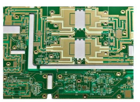
Since PTFE is expensive and more difficult to work with, most designs use it only where the radio actually is. A mixed stack with PTFE for the RF layers and FR4 for the digital and power layers is common, and it is a reasonable compromise, but it introduces the transition between the two materials as a design element. The transition is an impedance discontinuity and a mechanical interface with different expansion, so it has to be modelled and the reference plane kept continuous across it. Where the transition cannot be avoided, it should be placed where the impedance change is least damaging, and the transition itself should be verified on a prototype.
PTFE and the Finished Assembly
A PTFE board is not finished when it leaves the fabricator. The material’s expansion continues to matter at assembly, where the board sees a reflow excursion and then the thermal cycles of its service life. The plated barrels that see the most strain are the ones that connect layers with a large dielectric thickness, so a design that needs a thick PTFE build should keep the critical transitions short and avoid vias that pass through the full stack. Where the assembly also carries a large metal component or a connector, the mismatch in expansion between the component and the board has to be considered, because a PTFE board moves more than an FR4 one and a rigid attachment can crack the dielectric or the joint over repeated cycles. The qualification that matters for these boards is thermal cycling of the actual assembly, not a material datasheet comparison.
FAQ
Why does PTFE need different drilling? Because it is softer and smears rather than cuts, so sharp tools and different parameters are needed to produce a wall that will plate reliably.
How is the surface prepared for plating? With a chemical or plasma treatment that makes it wettable and keyable, since copper does not bond directly to PTFE.
Does the material move more? Yes. The higher expansion and lower stiffness make registration harder, so a larger annular ring is required.
Can PTFE be mixed with FR4? Yes, and it is common, but the transition between the materials has to be modelled and placed deliberately.
What does PTFE cost? More per panel than FR4, and more again in process, since drilling, plating and lamination all need different parameters.
Conclusion
PTFE is an electrical material with a difficult process, so the benefits have to justify the fabrication constraints and the design has to allow for them. Give the ring more tolerance, specify the dielectric thickness and its tolerance, avoid stacked vias, and treat a mixed stack as a design element rather than a purchasing shortcut. Material options are listed under PCB capabilities, the process differences are described in PCB manufacturing, and the RF layout rules belong to PCB design and layout. Radio boards are normally proven through prototype PCB assembly in 2026.