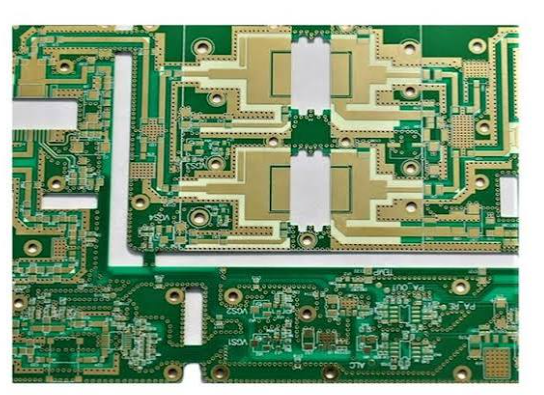
Metal Core PCB: Design and Thermal Path
What a Metal Core Board Is
A metal core board uses a metal plate, usually aluminium and sometimes copper, as the base instead of the usual FR4 laminate. The circuit is built on a thin dielectric layer bonded to the metal, and the metal serves as the mechanical support, the heat spreader and, in some designs, one of the electrical layers. The construction is used where a component dissipates enough heat that an FR4 board cannot spread it away, which is the case for high-power LEDs, motor drivers, power supplies and some automotive circuits.
The Dielectric Layer
The dielectric is the critical element. It has to insulate the circuit from the metal, it has to bond reliably to both surfaces, and it has to conduct heat as well as possible, since it sits directly in the thermal path. Its thermal conductivity is typically several times that of FR4, which is what makes the construction work, but it is still far below that of copper, so it is often the largest single thermal resistance in the assembly. Its thickness is a compromise between dielectric strength, which favours thickness, and thermal resistance, which favours thinness. The most common failure of a metal core design is to treat the board as though the metal were in direct contact with the heat source, when in fact the dielectric is the limiting element.
Thermal Path and Spreading
The heat path runs from the component, through the solder joint, through the copper pad, through the dielectric, into the metal base, and then out to the environment. The metal base spreads heat laterally, which is its main advantage: a large aluminium plate can spread a concentrated heat source over a wide area and reduce the heat flux that a downstream heatsink has to handle. Where the base is also the mounting surface, it can transfer heat directly into a chassis, which is often the best path available in a small enclosure. The design rule that follows is that the copper area under the component should be as large as the layout allows, because it feeds the dielectric and the metal, and the metal base should be as large as the mechanical design permits.
Single-Sided and Multilayer
Most metal core boards are single-sided, because building multiple layers on the dielectric is possible but adds cost and reduces the thermal benefit. Where a design needs both a thermal base and two signal layers, the usual approach is a metal core with a single circuit layer plus a second conventional layer bonded on top, or a metal-backed board with the metal acting only as the spreader. Where the metal base is used as an electrical layer, the dielectric has to provide the isolation, and the voltage rating of the dielectric becomes a safety parameter rather than a thermal one.
Mechanical and Assembly Effects
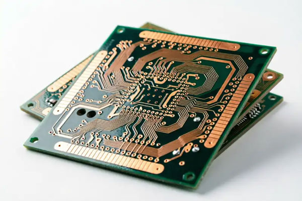
The metal base is stiffer and heavier than an FR4 board, and it expands differently from the dielectric and from the components. A large aluminium panel expands significantly over a reflow cycle, which stresses the dielectric and the joints, and the assemblies are usually reflowed with a longer, gentler profile or by a different method. Where the board is mounted to a chassis with screws, the thermal expansion of the metal has to be allowed for, or the assembly will bow or crack the dielectric over time. Single-sided construction also means that through-hole parts on the metal side are not possible without an insulating sleeve or a punched clearance, which changes the mechanical design.
Design Rules
Maximise the copper area under and around the heat source to feed the thermal path. Keep the dielectric thickness at the minimum the voltage requires, since every extra micrometre adds thermal resistance. Use thermal vias where the design allows, though on a single-sided metal core the metal itself is usually the path. Allow for the expansion of the base in the mechanical design, and specify the mounting method rather than leaving it to the assembler. Keep the outline and any cut-outs in the metal consistent with the mechanical drawing, since the metal is machined rather than laminated and the tolerance is different. Where the board carries an LED array, the thermal design should be checked by measuring the junction or the case temperature rather than by calculation alone.
Where It Beats FR4
A metal core is worth its cost when the heat flux is too high for an FR4 board to spread, when the board itself is the mounting surface and has to conduct into a chassis, when the temperature rise has to be kept low for the reliability of the components, and when the application has a mechanical requirement for stiffness. It is not worth it where the heat is modest and the board is doing fine on FR4, since the construction costs more, offers less routing density and constrains the assembly process. The comparison should be made with the actual thermal resistance of each option rather than with a general preference for a metal-backed construction.
Metal Core and the Assembly Process
The assembly of a metal core board differs from an FR4 assembly in ways that are easy to underestimate. The board is a heat spreader, so it takes longer to reach reflow temperature and it cools more slowly, which changes the profile in both directions: the ramp has to be gentler to avoid stressing the dielectric, and the cooling is slower than the oven expects. The board is also heavy, which affects the conveyor, the placement machine and the fixtures, and it is stiff, which means it does not conform to a slightly uneven support surface. Where the design has components on the metal side, they are often attached with a thermally conductive adhesive rather than by soldering, which is a different process with its own cure schedule. The practical lesson is that a metal core assembly should be planned with the assembler at the design stage rather than handed over as an FR4 equivalent.
FAQ
What is a metal core PCB? A board built on a metal base, usually aluminium, with a thin thermally conductive dielectric between the metal and the circuit.
What limits the thermal performance? The dielectric layer, which is far less conductive than copper and sits directly in the heat path.
Can a metal core board be multilayer? It can, but most are single-sided, since additional layers add cost and reduce the thermal advantage.
Why does the assembly change? Because the metal base expands more than the laminate and is stiffer, so the reflow profile and the mounting method have to allow for it.
When is a metal core worth the cost? Where the heat flux is beyond what FR4 can spread, or where the board doubles as a mounting and heat-transfer surface.
Conclusion
A metal core board is a thermal solution, and its benefit depends on the dielectric as much as on the metal, so the design should maximise the copper that feeds the path and minimise the dielectric thickness consistent with the voltage. Allow for expansion in the mechanics and verify the result by measurement. Thermal substrates are described under PCB capabilities, the fabrication steps in PCB manufacturing, and the thermal layout belongs to PCB design and layout. Power assemblies are normally proven through prototype PCB assembly in 2026.