AI Motherboard PCB Design: Signal, Power and Thermal Limits
A board built around an accelerator is not simply a bigger version of a processor board. Three characteristics change at once: the data rate between the device and its memory and network interfaces moves into the tens of gigabits per lane, the power drawn by a single package can reach several hundred watts, and the device density makes the routing between them a multi-layer problem rather than a placement problem.
The result is that the design has to satisfy three requirements simultaneously, and the three interact. Improving the signal path by adding layers changes the thermal structure. Improving the thermal path by adding metal in one place changes the impedance of the traces above it. Working on one pillar in isolation is how a design reaches its fifth revision.
Signal Integrity at These Rates
At these edge rates the trace is a transmission line and the familiar problems acquire new magnitude. Loss in the dielectric and in the copper attenuates the high frequency content of the signal, which closes the eye at the receiver. Reflections occur at every impedance discontinuity: a via, a connector, a change in trace width, a pad. Crosstalk between adjacent traces adds to both.
Three techniques address them. The laminate is chosen for its electrical properties rather than its mechanical ones, which makes the choice a fabrication capability question as well as a design one, using a low loss material family whose dielectric constant and loss tangent are specified across the frequency band of interest. Impedance is controlled explicitly for each class of net, from the geometry of the trace through the dielectric thickness, and verified with a coupon on the production panel.
Interconnect structure is designed rather than accepted. Parallel buses are matched in length so their bits arrive together, and point to point serial links are given the topology their controller requires. Vias are treated as components: a deep through hole leaves an unused stub that resonates at a frequency determined by its length, so a back drill operation removes the stub, or a blind via formed by laser stops where the signal exits.

Power Integrity for Hundreds of Watts
The current is only half of the problem. The device can move from a light load to a full load within nanoseconds, and the supply has to deliver that current without the voltage at the die moving outside its window. Simultaneous switching inside the package adds noise on top of the supply ripple, and the resistance of the distribution path produces a static drop that reduces the margin before anything dynamic happens.
The response is layered. The stack-up carries dedicated, continuous power and ground planes so that the distribution has a low impedance over a wide band. A decoupling network is placed as close to the device as the layout permits, combining bulk capacitance for the low frequency content with ceramic capacitors that respond quickly, and the impedance of the connection matters as much as the capacitance value.
The distribution is then analysed rather than assumed. A direct current analysis of the power distribution after routing shows where the voltage drop is concentrated and which necks or via groups are responsible, and the correction is usually geometric: more copper, more vias, a shorter path. The same analysis identifies the current density, which is what actually sets the local temperature rise.
Thermal Design Is a Copper Problem
Heat leaves the die through the package, and the board is one of the paths it can take. The common solution is an array of thermal vias beneath the package pad, which carries heat from the surface copper to the inner planes and to the opposite side of the board, where a larger area can dissipate it. The vias have to be filled or capped appropriately so that the pad remains a flat surface for the assembly process.
Copper area then does the work: exposed copper beneath the device, sometimes with a metal heat spreader attached, and inner planes thermally connected to the same structure. For the most demanding cases the substrate itself changes, either to a metal backed board or to a laminate with higher thermal conductivity. Those choices are taken early, because they change the electrical design as much as the thermal one, particularly the achievable impedance and the drill capability.
<img src="https://www.gopcba.com/wp-content/uploads/2025/08/7502-1-scaled.png" alt="thermal via array under a package” />
The Order the Work Has to Happen In
Simulation precedes the first trace. The stack-up, the materials and the routing rules for each net class are decided against a model, because changing them after the routing exists means starting again. Placement follows, and its purpose is to shorten the critical paths: the accelerator, its memory, the power stages and the high speed connectors have to sit where the interconnect between them is as short and as controlled as the architecture allows.
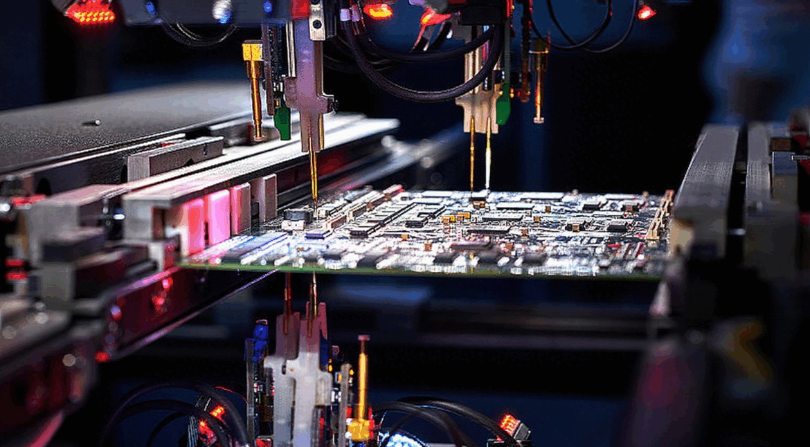
Routing is then done in order of difficulty. The most critical differential pairs and clocks are routed first, while the board is empty and the geometry is still free, followed by the remaining high speed buses, and finally the low speed signals and the supply distribution. Post-layout verification extracts the interconnect models and checks the eye, the ripple and the drop, using the same measurement discipline the production test will apply, and the design is only complete when the fabrication package includes the impedance requirements, the stack-up definition and the process notes that make the board reproducible.
The handover to manufacturing is part of the design rather than an administrative step. A stack-up that depends on a drill capability the fabricator does not have, or an impedance that requires a dielectric thickness outside the process window, will be changed by someone during production, and the performance promised by the simulation will not be the performance delivered. Confirming the capability before the constraints are frozen is the cheapest way to keep the two aligned. The same principle applies to the assembly stage, where the paste deposit and the placement accuracy have to suit the finest pitch on the board.
FAQ
Does a board of this class always need more than twelve layers? The count follows the number of net classes, the plane requirements and the escape density of the packages, and it is decided by simulation rather than by convention.
Why is back drilling necessary? It removes the unused portion of a through via barrel, which otherwise acts as a stub that resonates within the band of interest.
Can a metal backed board help with both heat and impedance? It can help thermally, but it constrains the stack-up and is normally used where the thermal requirement dominates.
When should the direct current analysis be run? After the power distribution is routed and before the design is released, and again whenever the load estimate changes.
Summary
An AI motherboard PCB is defined by the interaction of three requirements: a signal path that survives multi-gigabit rates, a power distribution that supplies several hundred watts without moving, and a thermal structure that carries the heat out of the package. Each is addressed with materials, geometry and simulation, and none of them can be solved after the others have been fixed. Decide the stack-up and the materials first, simulate before routing, and confirm the fabrication capability before the design is released.