SMT Prototype Builds: Data Intake, Stencil and First Article Release
A prototype order is small by definition, and that is exactly why it deserves the full process. The purpose of an SMT prototype build is not merely to produce a board that powers up. It is to verify that the packages in the bill of materials match the footprints, that the orientation data is correct, that the coordinates are right, that the joints can be formed and that the testing that follows can actually be executed. A project that hand repairs a paste starved joint on the prototype and moves on has a working board and an unsolved process, and the same defect will reappear in the volume order where it can no longer be handled one board at a time.
The Data the Order Needs
The Gerber data, the bill of materials, the placement coordinates, the assembly drawing, the quantity and the delivery date are the base set. The bill of materials should carry the full part number, the reference designator, the package, the manufacturer and any substitution requirement, and the assembly drawing has to mark the direction of the integrated circuits, the diodes, the electrolytic capacitors and the connectors.
Where programming and functional testing are required, the programme file, the target device, the programming interface, the supply conditions, the test sequence and the acceptance criteria come with the order. The earlier that material is complete, the more likely it is that the prototype can move straight into verification rather than waiting for a harness or a firmware revision.
At intake, the Gerber data, the bill of materials, the coordinates and the assembly drawing are checked against each other. A missing reference designator, a package that does not match the footprint or an unclear polarity marking is raised with the customer before the order is scheduled, because each of those is a conversation at that point and a batch of scrap later.

The Stencil and the Material Still Matter
The stencil is evaluated from the pads, the packages and the spacing between components. A quad flat no-lead thermal pad, a fine pitch integrated circuit and ordinary passive components each need a different opening, and a small order is not a reason to skip that analysis. A stencil that has been designed for one of the three produces a defect rate that looks like a placement problem and is actually a printing problem.
Material preparation confirms the full part number and the packaging form. Loose parts, integrated circuits removed from their original reel and quantities that equal the finished requirement with no allowance for loss all affect the feeder setup and the practical yield. Where a critical component is short, that is worth raising before printing begins rather than after the paste has been deposited.
After the first board is printed, the paste inspection step shows the area, the volume and the offset of the deposit. When the same region repeatedly shows too little paste, the stencil, the board support and the printing condition are examined before placement continues.
Releasing the First Article
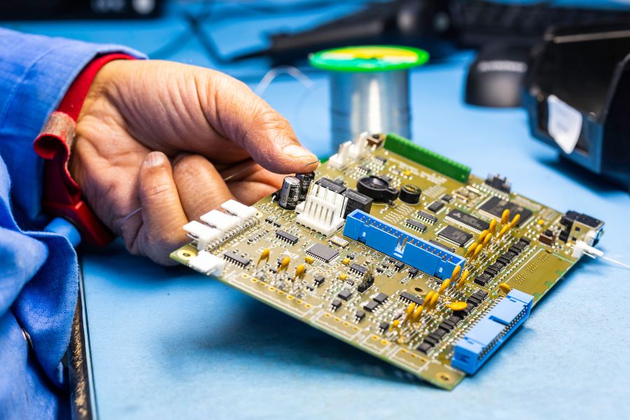
After the first board has been placed and reflowed, the part numbers, the orientation, the position and the condition of the joints are confirmed against the bill of materials and the assembly drawing. The polarised components, the fine pitch integrated circuits, the connectors and any substituted part are the positions that receive the closest attention.
The first article is also reviewed against the optical inspection result by a person. When the machine reports an offset, a missing part, a bridge or a tombstone, the physical board is examined and the decision is recorded. If the cause is a coordinate, a stencil or a programme issue, the production setup is corrected before the remaining boards are built, because a prototype order is the last place where a systematic fault is still cheap to fix.
Where programming and testing are part of the order, the first article continues into those steps. A board whose appearance is perfect but whose programme will not connect, or whose connector is mounted the wrong way round, has not yet proved that the design is ready.
Feeding the Findings Back
The problems found on a prototype have to be classified before they can be closed. A pad that is the wrong size for the component is a design issue and returns to the layout. A coordinate angle that is wrong is a data issue and is corrected in the file. A substitute part whose package does not match is a material issue and requires the specification to be reconfirmed. A paste or placement problem that repeats is a process issue and is corrected in the setup. Treating all four as the same kind of problem is how a defect survives into production.
A board that has been reworked repeats the corresponding inspection and functional test before it is released, because restoring a component to its correct position does not cancel the thermal and electrical stress it has already seen.
When the project moves into volume, the confirmed Gerber data, bill of materials, coordinates, programme and test requirements become the production revision, and the temporary notes written during the prototype build are retired. A small batch run is also where that handover is easiest to make, since the settings that were proven are still attached to the order. Our rapid PCBA prototyping group runs these builds, SMT assembly carries them into volume, the assemblies are tested under PCBA testing, the components come through component procurement, and the records are held under quality management.
Why the Small Order Repays the Full Process
It is reasonable to ask why a handful of boards should go through a data check, a DFM check and a stencil review that a volume order would also receive. The answer is that the prototype is the only build in which every one of those findings can still be acted on cheaply. A footprint that is too small for its component is a layout change while the artwork is open and a scrap decision once the panels have been fabricated. A coordinate that is rotated is a file correction on a prototype and a batch of reversed parts later.
The solder paste printing parameters follow the same logic. The stencil thickness, the opening geometry and the support beneath the board are decided for the product and recorded, so that the second build starts from the settings that produced an accepted board rather than from a fresh setup. The inspection of the deposit, the investigation of a repeated anomaly and the confirmation of the first article are all part of the same record.
Nothing in that process depends on the size of the order, which is exactly the point. The process exists to move the uncertainty from the production phase, where it is expensive, to the engineering phase, where it is not.
FAQ
Is a prototype order worth a full DFM check? Yes. It is the cheapest point at which a footprint, coordinate or stencil problem can be found, because the quantity is small and the batch has not been committed.
Why not simply repair the first board and proceed? Because a repair removes the symptom and leaves the cause. The same fault returns at volume, where it costs far more to correct.
What makes a prototype ready to transfer to production? Confirmed Gerber data, bill of materials, coordinates, programme and test requirements, with the settings that produced the accepted board recorded against the order.