PCB Slot Design Rules and Edge Routing
A slot is a cut in the board that is not a hole and not the outline. It may separate a high-voltage section from a low-voltage one, allow air to move across a hot component, provide a mounting feature, or define a breakaway tab. Because a slot affects both the electrical behaviour and the mechanical integrity of the board, its geometry has to satisfy the fabricator, the assembler and the electrical design at the same time.
What Slots Are For
Electrical isolation is the most common reason to cut a slot. A long narrow cut more than doubles the creepage distance between two regions on a board, because the surface path must travel down one wall, along the base of the slot and up the other side. Where the working voltage is high enough that a surface tracking path is a hazard, a slot is often cheaper than a piece of equipment rated for a larger spacing.
Mechanical and thermal uses are almost as common. A slot can create space for a heatsink, a screw or a cable, or allow a connector to protrude through the board. Ventilation slots increase airflow across a hot area, and in some designs they are the primary thermal path for a component that cannot be heatsunk.
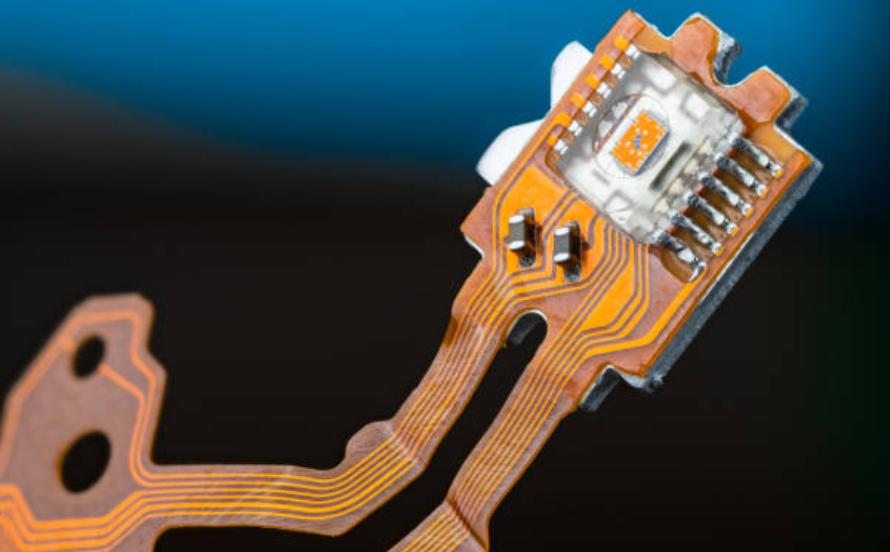
Slots also serve assembly and structure. A narrow slot provides a rail for a flexible circuit to enter, a groove for a battery tab, or a breakaway feature between a board and its tooling strip. Each of those purposes places different demands on the geometry, and a slot that satisfies one requirement may conflict with another, which is why the purpose of every cut should be recorded on the drawing rather than assumed.
Creepage Isolation Slots
Where a slot is used for creepage isolation, the dimensions follow from the required withstand voltage. The wall thickness of the slot is not the issue; what matters is that the slot is long enough, and deep enough where a partial-depth slot is used, that the surface path cannot bridge the two regions under contamination.
The routing near the slot is equally important. Copper must be kept back from the slot edge by the same distance that would apply to the board profile, so no plating or debris can form a bridge across the cut. Vias must not be placed in the slot, and the ground plane should not extend into it in a way that leaves a floating tab of copper along the wall. The clearance rules that apply to the board edge and to copper in general are set out in this discussion of via to trace clearance.
Routed Edge and Router Bit Limits
The routed edge of a board is produced by a milling cutter following the profile, and the tool has a diameter. Every internal corner of the profile, and every internal corner of a slot, therefore carries a radius of at least half the tool diameter. A design that specifies a square internal corner is asking for a geometry the process cannot produce, and the fabricator will either radius it without asking or return the design.
The same constraint sets the minimum width of a slot. A slot narrower than the tool cannot be machined at all, and a slot only slightly wider than the tool leaves a fragile cutter path and produces a poor finish. Slot widths should be specified generously at the design stage, and the fabricator should be consulted about the tool sizes available before the outline is frozen.
Narrow sections of board created by slots need attention as well. A slot that leaves a thin strip of laminate between itself and the board edge produces a section that flexes during handling and can crack. Where such a feature is unavoidable, the strip should be supported during assembly or the geometry adjusted so the remaining material is thicker.
Tooling Holes and Assembly Features
Fabrication and assembly both need features that are not part of the circuit. A tooling hole is a non-plated hole used to locate the panel during drilling, routing, printing or placement. Tooling holes are placed outside the board area on the tooling strip, and they need clearance around them so that the locating pin can engage and release without binding.
The other common assembly feature is the fiducial, a copper mark with a clear area around it that the placement machine uses to establish its coordinate system. Fiducials are usually required in at least three positions per panel, and on each board where the panel is large. Their position and their clear area are specified by the assembler rather than chosen by the designer, and they interact with the mechanical constraints on the board outline, which are discussed in this article on board outline and mounting design.
Panelization and Routing Direction
Slots and profiles are created in a single routing operation across the panel, so the direction in which the features run affects both the tool path and the panel strength. Where a panel contains several boards with slots, aligning the slots in the same direction allows the router to follow a continuous path and reduces the time and cost of the operation.
Tabs, the small bridges that hold a board within its tooling strip, are part of the same decision. Tab position determines where the board breaks away and therefore which edges are clean and which carry the burr. A tab placed on an edge that must mate with a connector is a source of mechanical interference, and a tab placed near a component is a source of stress during depanelling. The general principles that govern connector escapes and mechanical stress at the board edge are described in this discussion of escape routing and pad fanout.
Final Checks
Before the outline is released, confirm that every internal corner has a radius at least half the router diameter, that every slot is wider than the minimum tool and wider still where possible, that copper is kept clear of every slot and profile edge by the required distance, that no via or component sits inside or adjacent to a cut, and that the tooling holes and fiducials are in positions that do not conflict with the electrical layout.
FAQ
Can a slot be used to increase creepage distance? Yes, and it is often the most economical way to do so. A narrow cut more than doubles the surface path between two regions, because the path must travel down one wall, across the base and up the other side. Copper must be kept well clear of the slot edges to prevent bridging.
Why does a slot have a minimum width? Because the profile is milled with a cutter of finite diameter. A slot narrower than the tool cannot be produced, and one only slightly wider produces a poor finish and a fragile path for the cutter. The available tool sizes should be confirmed with the fabricator before the geometry is fixed.
Do internal corners on a slot need a radius? Yes. Every internal corner carries a radius of at least half the router diameter. A drawing that specifies a square internal corner cannot be manufactured as drawn and will be modified by the fabricator, so the radius should be included in the design.