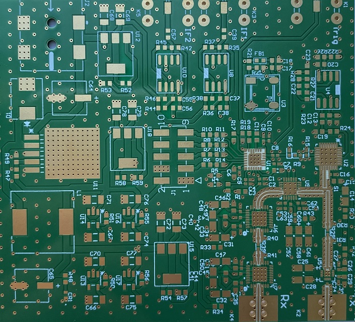
Automotive PCB Design Requirements: Reliability, Materials, and Standards
Automotive electronics stopped being a niche corner of PCB engineering once electric and hybrid powertrains, radar sensing, camera modules, and driver assistance systems became standard content. A modern vehicle carries dozens of control units, and each one has to work reliably for the life of the vehicle under conditions that consumer hardware is never exposed to. Automotive PCB design is therefore defined less by the schematic than by the environment the finished board must survive.
The requirements that shape the design come from three directions: the quality system the manufacturer must operate under, the physical environment the board must endure, and the mechanical pressure to make every unit smaller and lighter. Understanding how those three pressures interact is the starting point for every decision that follows.
What the Vehicle Environment Actually Demands
An automotive board lives through temperature extremes, thermal cycling, humidity, salt spray, vibration, mechanical shock, and conducted and radiated noise from the rest of the vehicle. Engine-adjacent electronics see the widest temperature excursion, while body electronics see the most humidity and condensation. Cabin modules trade thermal stress for a substantially longer duty cycle, since they may be powered the entire time the vehicle is in operation.
The practical consequence is that every parameter has to be specified with margin. A connector rated to the maximum operating temperature of the cabin is not automatically suitable under the hood. A solder alloy selected for ease of assembly is not automatically suitable where joints will see thousands of thermal cycles over a decade of service. The board is qualified against the environment, not against a laboratory condition.
Quality Management System Requirements
The automotive supply chain imposes a quality management system on every tier, and printed circuit board fabrication is inside that scope. The sector-specific requirements that grew out of the earlier ISO/TS 16949 framework are now consolidated into IATF 16949, which places emphasis on defect prevention, process control, and traceability rather than on final inspection alone.
For a board designer the practical effects are documentation and change control. Material lots are traceable to a production date, process parameters are recorded per panel, and any change to a laminate, a solder mask, or a surface finish has to be re-qualified rather than substituted quietly. Designs that assume free substitution of equivalent materials will fail the qualification audit even when the electrical performance is unaffected.
A further implication is that reliability data has to accumulate across builds. Field returns, thermal cycling results, and process capability indices feed back into the design rules, which is why automotive programs tend to keep conservative design margins compared with consumer projects.
Reliability Across a Ten to Twelve Year Service Life
Passenger vehicles are expected to remain in service for ten to twelve years, and during that time only wear items are replaced. The electronics and the board must therefore have a service life comparable to the vehicle itself, which puts wear-out mechanisms such as via barrel fatigue, conductive anodic filament growth, and solder joint cracking directly on the critical path.
Design for reliability in this context means selecting structures that degrade slowly. Plated through-holes need adequate copper thickness in the barrel so that thermal cycling does not accumulate fatigue damage. Laminate and prepreg selections need a glass transition temperature well above the maximum board temperature, with enough remaining margin that the material never enters a state where its expansion behavior changes abruptly. Interconnect structures should avoid unnecessary stress concentrators, and via-in-pad or microvia stacks should be qualified with cross-sections after thermal stress rather than accepted on the basis of the fabricator’s standard process.
Thermal Cycling and Substrate Selection
Thermal cycling is usually the dominant wear mechanism on an automotive board, because the coefficient of thermal expansion of the laminate differs from that of copper, the solder, and the component package. In a plated hole the barrel expands less than the surrounding resin, so each cycle adds a small amount of plastic strain to the copper. The number of cycles to failure falls steeply as the temperature excursion grows, which is why an under-hood module with a wide excursion requires more copper in the barrel than a cabin module with the same electrical duty.
Material selection and via geometry therefore have to be evaluated together. Thicker laminate means longer barrels and more accumulated strain, so a design that needs a thick board for rigidity should also specify a higher copper plating thickness, a lower-expansion laminate, or a design change that spreads the thermal load across more vias. Surface finish matters as well, because the joint between the pad and the solder determines how much of the package stress reaches the plating.

Where a joint must survive a very large number of cycles, the choice of solder alloy and the thermal mass of the surrounding copper both change the outcome. Related trade-offs are covered in lead-free versus leaded solder.
Weight Reduction and Miniaturization
Every gram removed from a vehicle improves efficiency, and electronics are an attractive target because they are distributed throughout the body. Reducing board area and thickness is achieved through three levers: increasing routing density so that fewer layers are needed, reducing the outline area by moving to finer-pitch packages, and reducing thickness where mechanical requirements allow it.
The limits are set by reliability rather than by fabrication. Thinner boards are more flexible, which transfers mechanical strain to solder joints, and denser routing reduces the copper cross-section available for current and heat. A design that reduces board thickness by twenty percent without revisiting the copper distribution will usually trade a small weight saving for a large reduction in thermal cycling life.
Substrate Selection: Ceramic Substrate or Resin Laminate
Automotive boards divide broadly into two families. A ceramic substrate offers high heat resistance and excellent dimensional stability, which suits power modules and high-temperature locations such as exhaust-adjacent sensors. The penalties are cost and manufacturability: ceramic panels are smaller, more brittle, and harder to process into fine features, so the cost per square centimeter is significantly higher than a polymer laminate.
Resin-based laminates with improved heat resistance have taken over most of the vehicle, because they combine adequate thermal performance with the density and panel efficiency needed for high-volume production. A useful rule is to reserve ceramic for the locations where the junction or ambient temperature genuinely exceeds what a resin system can tolerate, and to use the laminate elsewhere.
Matching Board Type to Vehicle Function
Different vehicle systems tolerate different board constructions. Powertrain control and high-temperature sensing favor materials with the highest thermal capability. Body control, infotainment, and comfort electronics are dominated by cost, density, and immunity to humidity. Safety-critical systems such as braking and steering add redundancy and diagnostic coverage, which changes the layout because duplicated channels must be routed independently rather than sharing a common reference.
Whatever the application, current carrying capacity has to be calculated with temperature derating rather than at ambient. Copper resistivity rises with temperature, and a trace sized at twenty-five degrees will exceed its allowed temperature rise in a hot enclosure. The calculation method is described in trace width and current calculation.
Protection, Coating, and Long-Term Insulation
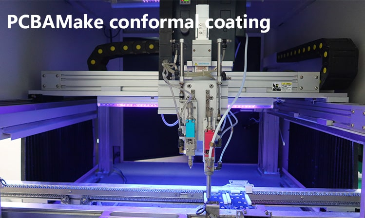
Humidity, condensation, salt spray, and chemical exposure attack the board surface rather than the bulk material. Conformal coating is the standard countermeasure, and it is only effective when the coating can wet every surface uniformly. That requirement feeds back into layout: tall components should not shelter adjacent pads, keep-out areas around connectors have to be defined, and no residue-trapping pockets should be created by component placement.
Spacing rules also have a role. As spacing shrinks, the electric field between adjacent conductors grows, and contamination plus moisture can bridge them. For automotive work the spacing should be chosen with the pollution degree and the working voltage in mind, with additional margin on nets that carry battery voltage or a switching node. Protection strategies for exposed assemblies are discussed in conformal coating and board protection.
Bringing the Requirements Together
Automotive board design converges on a small set of habits: generous margin on temperature and current, conservative via and plating structures, continuous reference planes, filtering at every interface, and documentation that survives an audit. None of these choices is individually difficult. The difficulty lies in the fact that each one costs area, weight, or flexibility, and the trade has to be justified against the environment the board will actually see rather than against the prototype bench.
FAQ
Do automotive boards always need a thick copper plating in the vias? Not always, but the barrel thickness should be chosen from the expected number of thermal cycles, not from the minimum the fabricator can produce. Under-hood modules with wide temperature excursions justify a thicker barrel; a cabin module operating in a narrow, controlled range can use a lower figure provided the qualification testing supports it.
When is a ceramic substrate worth the cost? When the ambient or junction temperature genuinely exceeds what a heat-resistant resin laminate can survive, or when dimensional stability under temperature is the limiting performance factor. For everything else, improved resin systems deliver adequate thermal performance at much lower cost and with better density.
How much does miniaturization actually affect reliability? The effect is indirect but real. Denser routing reduces copper cross-section, thinner boards increase the mechanical strain transferred to solder joints, and smaller outlines concentrate heat. Reliability testing after a size reduction should therefore cover thermal cycling and vibration rather than just functional performance.