Common Impedance Coupling: Grounding Techniques That Suppress It
Ground is supposed to be the quiet reference that every signal is measured against. In practice it is a conductor with resistance and inductance, and when two circuits share a portion of it, the current from one appears as a voltage in the other. This mechanism, called common impedance coupling, is responsible for a large share of the noise problems that survive every attempt to fix them with better decoupling. Suppressing it requires understanding where the shared current flows, not simply adding capacitance.
The basic arithmetic explains why the effect is so persistent. A shared ground return segment has a small resistance and a small inductance, but the currents involved are large and fast. A ground path with 10 nanohenries of inductance carrying a 1 ampere step in 1 nanosecond produces 10 volts of transient shift, which is more than enough to corrupt a logic threshold or to inject noise into a sensitive analog input.
How the Coupling Mechanism Works
The effect appears whenever two or more current loops share a common conductor. The return current from circuit A flows through the shared segment and produces a voltage across it. Because that same segment is part of the return path for circuit B, the voltage appears in series with circuit B’s signal and adds to it.
Two versions matter in board design. Resistive coupling dominates at low frequency, where the impedance of the shared path is set by its resistance and the resulting error is proportional to the DC or low-frequency current. Inductive coupling dominates above a few megahertz, where the impedance of the same path rises with frequency and the error becomes proportional to the rate of change of current. The second version is the one that ruins digital designs, because a switching edge contains high-frequency content regardless of the clock rate.

The path involved is rarely obvious. A ground return can be shared through a plane that is connected in more than one place, through a single via that serves several nets, or through a connector pin that carries the return for two different interfaces. Locating it usually requires thinking in terms of loops rather than in terms of nets.
Single-Point Grounding for Low-Frequency Circuits
Single-point grounding is the countermeasure for low-frequency circuits. The ground connections of all circuits at the same level are brought together at one point, so that no two circuits share a conductor between that point and their own local ground reference. The return currents then flow only through their own branches and meet only at the reference node.
The method has a frequency limit. Above roughly 1 MHz, the inductance of the individual branches becomes significant and the arrangement stops behaving as a common reference. Where a single-point scheme must be used between 1 and 10 MHz, the ground branch lengths should be kept below one twentieth of the wavelength of the highest significant frequency, which at 10 MHz is about 1.5 meters, and considerably less once the dielectric constant of the board is taken into account.
Multi-Point Grounding for High-Frequency Circuits
Above roughly 10 MHz the analysis reverses. Long individual ground branches behave as antennas and as inductors, so the goal becomes the shortest possible return path rather than a single reference node. Each circuit connects to the ground structure at the nearest point, which minimizes loop area and therefore both the inductance and the radiated field.
On a board this is implemented with a continuous reference plane. Because the plane has very low inductance compared with any trace, the voltage developed across it is small, and every circuit shares it without a significant penalty, which is what limits ground bounce to a few tens of millivolts instead of the volts that a narrow trace would develop. Where a plane is not available, a bus bar or a heavy copper rail can serve the same purpose; a bus-bar arrangement built from a silver-plated copper strip behaves as a low-inductance transmission structure and is a practical option in high-speed assemblies.
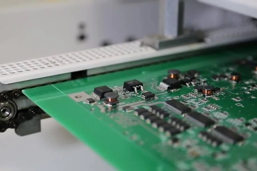
The multi-point approach also provides shielding. Filling unused board area with grounded copper reduces the inductance of the return structure and intercepts electric fields, which lowers both emissions and susceptibility. This is the reason a large-area ground is standard practice in high-frequency layouts, even when the schematic does not call for it.
Ground Trace Width and Geometry
A thin ground trace is worse than no deliberate ground at all, because its potential moves with the current it carries. A ground conductor that changes voltage with load is a reference that shifts under the signal, which destabilizes timing levels and degrades noise margin. Ground conductors should be at least 3 mm wide where a plane is not used, and wider where the current is large.
Geometry matters as much as width. Two ground traces running in parallel and connected at both ends form a loop that can carry circulating current and pick up magnetic fields, so a ground structure should be designed as a plane or as a properly terminated network rather than as a set of loose connections. Where a plane must be divided, the split should be defined deliberately in the schematic and the two regions joined at a single controlled point, so that no signal return crosses an unintended boundary. The interaction between ground impedance and harmonic current distribution is covered in ground current and harmonic distortion.
Separating Analog and Digital Returns
Mixed-signal designs need the digital and analog return paths to be separate where the noise-generating currents flow. The analog return should carry only analog current, the digital return should carry only digital current, and the two should meet at the supply reference rather than at an arbitrary point on the board.
The common failure is to split the ground plane and then route a digital signal across the split. The return current for that signal cannot follow its trace, so it detours around the gap, forming a large loop that radiates and couples into everything nearby. A split is only useful if no signal crosses it, and the place where the two grounds are joined must be chosen so that the analog return current does not have to share a path with the digital one. The general planning approach is described in ground routing and power trace planning.
Connector and Cable Returns
The same principle applies wherever signals leave the board. A connector that provides fewer return pins than it needs forces several signals to share a return path, and the shared inductance then couples them together. Provide a separate return for each high-speed signal group, and place the return pins adjacent to the signals they serve rather than at the far end of the connector.
Where a signal runs to a remote board or cable, the return path is a physical loop that is far longer than the on-board path. Reducing the loop area, by keeping the return conductor close to the signal conductor, is the most effective way to limit both emissions and susceptibility in that configuration. The same reasoning explains why the 3W spacing rule on a board pays dividends: widening the separation reduces the mutual coupling that would otherwise turn one trace into an aggressor for its neighbor, as described in the 3W crosstalk rule.
FAQ
Should I use single-point or multi-point grounding on a microcontroller board? Almost always multi-point, with a continuous ground plane. A modern microcontroller has edge rates whose frequency content extends well into the hundreds of megahertz, so the low-frequency assumption behind single-point grounding does not hold. Reserve single-point schemes for genuinely low-frequency analog circuits.
Can common impedance coupling be fixed by adding decoupling capacitors? Only partly. Capacitors reduce the impedance of the power delivery path, but they do not remove a shared ground return between two circuits. If a digital return current is flowing through the reference path of an analog circuit, that circuit will see the noise regardless of how well its supply is decoupled.
Is a ground plane always better than a ground grid? For a continuous reference, yes. A grid introduces gaps that force return currents to detour, which increases loop area. A grid can be useful when trapped volatiles or copper stress are a manufacturing concern on large surface areas, but an inner layer plane should remain solid.