EMC Immunity Testing: Radiated Field Susceptibility
Immunity is the other half of electromagnetic compatibility, and it is usually the harder half to test. Emissions can be measured without touching the product; immunity requires the product to be operating normally while a disturbance is applied, and the failure may be a subtle change in behaviour rather than a shutdown. EMC immunity testing therefore has to be planned as carefully as the design it verifies.
What Immunity Testing Verifies
An immunity test exposes the equipment under test to a disturbance and checks whether it continues to operate within defined limits. Conducted disturbances enter through cables and connectors. Radiated disturbances couple into the circuit directly, or onto the interface cables, which then act as antennas and deliver the energy to the electronics. When the amplitude of the radio frequency field is high enough, the induced voltage and the demodulated carrier can disrupt normal operation.
The purpose is not to prove that nothing happens, but to prove that what happens stays within the performance criteria defined for the product. Those criteria have to be written down before the test, because the judgement depends entirely on the intended function. A product that recovers by itself after the disturbance is treated differently from one that requires a power cycle, and the standard allows both outcomes to be declared acceptable if they are specified in advance.
Radiated Susceptibility and the Test Field
Radiated susceptibility testing is the longest and most difficult immunity test, and it needs expensive instrumentation and considerable experience. The manufacturer must supply the success criteria and a written test plan before the equipment arrives at the laboratory. The equipment is set up in its normal operating mode and in the mode in which it is most sensitive, and the field is applied in calibrated steps across the frequency range.
A typical range starts at 80 MHz and extends to 1 GHz, with some standards beginning at 27 MHz. The severity level is usually defined as a field strength of 1 V/m, 3 V/m or 10 V/m, although a product specification may carry its own requirements at particular problem frequencies. ESD and board edge protection belongs in the same planning conversation, because a board that is sensitive to radiated fields is usually sensitive to transients as well.
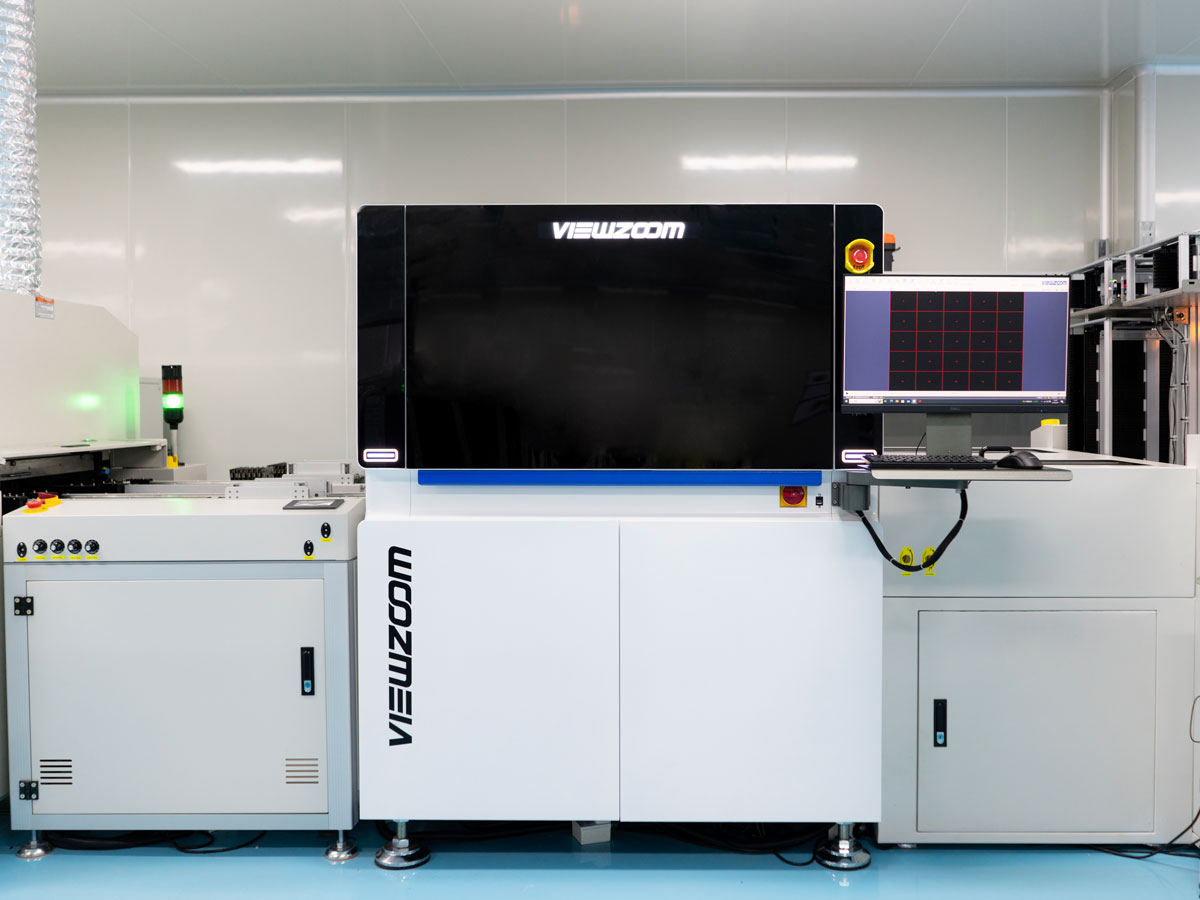
The test environment is what makes the result repeatable, and repeatability is the whole point of the standard.
The Uniform Field Requirement
The applicable immunity standard requires a uniform test environment to be established around the sample. That environment is created in an anechoic chamber lined with radio frequency absorbers, which suppress reflection and resonance so the field is uniform across the test volume. In an untreated room, reflections produce standing waves and the field gradient can vary by 20 to 40 dB, which means a sample can appear to fail suddenly at a very low field, and the test has poor repeatability.
Poor repeatability is not a neutral problem. It leads to over-testing, and over-testing leads to over-design, because the designer adds cost to satisfy a measurement artefact rather than a real requirement.
Absorber Types and Room Construction
Two absorber technologies dominate. Pyramidal absorbers are effective across a wide range, but their size is a problem: at 80 MHz the pyramid must be about 100 cm long, and to work down to 26 MHz it must exceed 2 m. They are also fragile, easily damaged by impact and flammable, and they cannot practically be used on the floor, because a sustained field above 200 V/m creates a fire risk.
Ferrite tile absorbers are far more space-efficient and work well at low frequencies, though their efficiency falls above about 1 GHz. They are dense, typically 100 mm squares around 6 mm thick, and they add significant weight to the walls, ceiling and door, so the mechanical design of the chamber matters as much as its radio frequency design. Being solid and non-combustible, they tolerate field strengths well above 1000 V/m, which is why they are preferred for high severity levels even though their performance falls off at higher frequencies.
Generating and Calibrating the Field
A high-power broadband amplifier drives a broadband antenna, typically placed about three metres from the equipment under test. Automated software controls the sweep and the calibration, and gives precise control of parameters such as sweep rate, frequency dwell time, modulation depth and field strength. Software hooks let the monitoring and the functional stimulation of the equipment be synchronised with the field, which matters when the failure criterion is a change in a monitored output rather than a loss of function.
Calibrating the field before the test is what makes the severity level meaningful. A field that has not been characterised is not a specification, and the return path planning inside the product is usually what determines whether a calibrated field produces a failure.

The practical difficulties are usually found in the auxiliary equipment rather than in the field generation.
Auxiliary Equipment and Cable Penetration
Stimulus equipment is needed to operate the product and to monitor its behaviour, and that equipment has to be immune to the same field. This is the inherent difficulty of radiated susceptibility testing. It becomes acute when the auxiliary equipment is complex and requires many cables and interfaces to pass through the wall of the shielded room.
Every cable that penetrates the room must be shielded or filtered so it does not compromise the shielding performance of the room, and so the field does not leak into the surrounding environment where it could interfere with spectrum users. Filtering data and signal lines is not always practical, particularly where the data rate is high or the number of lines is large, and that constraint has to be solved in the test plan rather than during the test.
Designing for Immunity
The design measures that improve immunity are largely the ones that improve emissions performance. Continuous return paths under every signal keep the loop area small and reduce the voltage induced by an external field. Filtering at connectors, where the cable meets the enclosure, keeps conducted energy out of the board. The grounding and shielding structure determines how much of the field reaches the sensitive circuitry.
Placing sensitive interfaces away from the connector area, and adding transient protection at the boundary, produces a product that passes the field test without a redesign. The principles of EMI suppression that apply to emissions are the same ones that build immunity, which is why pre-compliance testing early is far cheaper than discovering the problem in a certified laboratory late in the program.
FAQ
What is the difference between emissions and immunity testing? Emissions testing measures what the product radiates or conducts. Immunity testing applies a disturbance and verifies that the product keeps working within its defined performance criteria.
Why is a uniform field required? Without it, reflections create standing waves and the field varies widely across the test volume, so the result is not repeatable and can indicate a failure that would not occur in reality.
Can immunity problems be fixed after the test? They can, but the cost is high if the fix touches the enclosure, the connectors or the grounding structure. Designing the return paths and filtering at the start is much cheaper.