




ESD on PCB Edge Traces: Why It Happens
Electrostatic discharge testing produces some of the most instructive failures in board design, because the symptom and the cause are rarely in the same place. A product can pass every functional test and still reset during a contact discharge applied to its ground terminal — and the reason often turns out to be a signal trace that was routed a few millimetres from where it should have been.
The Case
A grounded desktop product was subjected to a contact discharge test at 6 kilovolts applied to the grounding terminal. The system reset. Disconnecting the Y capacitor that linked the ground terminal to the internal digital ground produced no clear improvement, which ruled out the obvious explanation and forced a closer look at how the energy was reaching the circuit.
Why the Ground Point Is Not at Zero Volts
Interference reaches a product’s internal circuitry by several routes, and the one that mattered here is counter-intuitive.
Because the test point was the ground terminal, most of the discharge energy flowed away through the ground lead. The discharge current did not flow directly into the internal circuit. That should have protected the board — except for the nature of the ground connection itself.
In a test arrangement of the kind defined by the IEC 61000-4-2 standard, the ground lead is roughly a metre long. A lead of that length has significant ground inductance, and the usual estimate is around one microhenry per metre – and at the frequencies involved, that inductance is the entire problem. When the discharge occurs, the current has an extremely fast rise time — under a nanosecond — and at those frequencies the inductance of the ground lead prevents the voltage at the connection point from dropping to zero.
That non-zero voltage at the ground terminal is what enters the product’s internal circuit. The board is not being hit by the discharge directly; it is being hit by the voltage that the discharge produces across its own ground connection.

The Coupling Path
The path can be described precisely enough to design against.
Two parasitic capacitances matter. The first is between the discharge point and the board’s ground. The second is between the board itself and the reference ground plane of the test setup. Together with the board’s working ground and the discharge generator, including its own ground lead, they form a closed loop through which a common-mode current flows — and the board sits in that loop.
The consequence is that the board is subjected to common-mode interference even though no discharge current passes through its signal circuitry. If the product also has other cables attached, the coupling is worse, because each cable provides another path for common-mode current.
The Trace That Caused the Reset
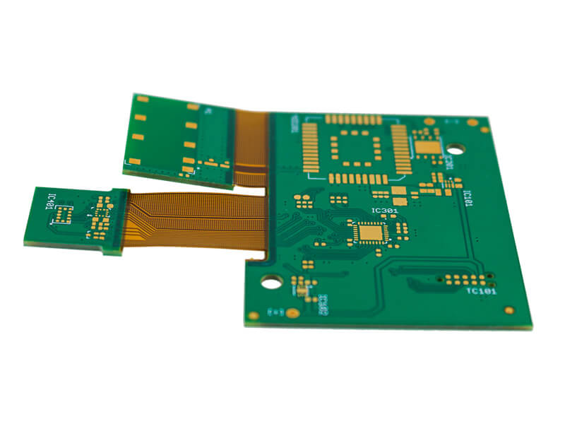
Inspection of the board revealed the mechanism. The reset control line from the processor was routed along the edge of the board, and it ran outside the coverage of the ground plane.
Any conductor on a board has a parasitic capacitance to the reference ground plane, and that capacitance is what couples common-mode interference into the signal. When a common-mode voltage appears on the board’s ground, an interference voltage develops between the trace and the ground. Its magnitude depends on two things: the impedance between the trace and the board ground, and the parasitic capacitance between the trace and the reference plane.
Hold the impedance constant and the relationship is simple: the larger the parasitic capacitance, the larger the interference voltage. That voltage adds to the working signal on the trace, and on a reset line a small addition is enough to trip the input.
Why Edge Routing Makes It Worse
The parasitic capacitance between a trace and the reference plane depends on the distance between them and on the equivalent area over which the electric field forms, following an approximate relationship of the form capacitance in picofarads equals 0.1 times the effective area in square centimetres divided by the height in centimetres.
Two consequences follow, and together they explain why the position of the trace matters so much.
First, a trace at the edge of the board has a favourable geometry for field formation: the distance to the reference plane below is unchanged, but the field is free to spread.
Second, a trace in the middle of the board is surrounded by other conductors, whose presence compresses the field and reduces the effective coupling area. A trace at the edge has no such neighbours on one side, so its field diverges relatively freely, producing a larger effective area and therefore a larger parasitic capacitance.
In this design, both effects were present at once: the reset line was at the edge, and it lay outside the ground plane, so it had no local reference to hold its potential relative to anything. The combination produced enough coupled voltage during the discharge to reset the system, which is exactly what the test observed.
The Fixes
Two remedies follow directly from the analysis, and both are cheap once the mechanism is understood.
The first is to reroute the conductor. Moving the reset line inward so that it lies within the area covered by the ground plane, and away from the board edge, reduces the parasitic capacitance by both mechanisms at once. To reduce it further, the remaining free area on the outer layer where the trace runs — the board in question was a four-layer design with the reset line on an outer layer — was filled with ground copper connected to the adjacent ground plane through a large number of vias. That local ground, tied down in many places, gives the trace a nearby reference and squeezes the field that would otherwise couple into the plane below.
The second is to add a capacitor on the affected line, close to the processor’s reset pin, with a value between about 100 picofarads and 1000 picofarads. The capacitor forms a low-impedance path at the interference frequencies and holds the line’s potential against fast transients. It does not replace the routing change; it is a supplement that costs almost nothing on a board that has the space.
What the Case Generalises To
Three lessons apply well beyond this product.
Signals that carry functional weight — reset, enable, interrupt, clock and reference lines — should not be routed near a board edge, and never outside the coverage of a reference plane. Their immunity is a property of geometry, and the geometry is free to get right at design time.
A ground plane protects only what it actually underlies. Copper that stops short of the board perimeter leaves the outermost traces with no local reference, which is precisely where they are most exposed. Keeping a margin between the plane edge and the board edge, and routing signals inside that margin, is the simplest defence available. The principles involved are covered further in this discussion of board level ESD protection layout.
Cables are part of the circuit for interference purposes. Any cable attached to the product provides a path for common-mode current, which is why a design that passes a test in one configuration can fail it in another. The board-level measures that reduce sensitivity have to be combined with the system-level ones, and the ground architecture that makes them work is described in this look at ground design types and rules.
Finally, the diagnostic lesson is worth keeping. The failure appeared at a ground terminal and the fix was in the routing of a logic signal, three levels of abstraction away from where the symptom was observed. Board-level immunity problems are usually solved by tracing the coupling path rather than by treating the symptom, which is why understanding the mechanism behind each countermeasure matters more than collecting them, as set out in this overview of EMI sources and coupling paths.
FAQ
Why did the discharge not damage the circuit directly? Because most of the energy flowed away through the ground lead. The damage mechanism was the voltage that the fast discharge current developed across the inductance of that lead, which then appeared on the board’s ground and coupled into signals.
Why is a trace at the board edge more sensitive than one in the middle? Because there are no neighbouring conductors to compress its electric field to the reference plane. The field spreads further, the effective coupling area increases, and with it the parasitic capacitance that couples interference into the trace.
Does adding a capacitor on the line solve the problem on its own? It helps by providing a low-impedance path at the interference frequencies, but it treats the symptom. Moving the trace inside the ground plane and away from the edge addresses the coupling mechanism itself, and the two measures are complementary.


1 Comment
PCB Design Principles for EMI Suppression
[…] Cables attached to the board are the other major radiator. A cable behaves as an antenna driven by whatever common-mode voltage appears at the connector. Keeping the connector ground connection wide and short, tying the connector shield to chassis ground with a low-inductance path, and filtering the signals that leave the board are all effective. The treatment of the board edge itself, where traces can pick up charge, is covered in this discussion of ESD and PCB edge traces. […]