PCB Stiffeners: Types, Materials, and Design Rules
A flexible circuit is designed to bend, and there are places where that is exactly what you do not want. Around a connector, under a component pad, or at the point where a board is inserted into a housing, the same flexibility that makes the circuit useful becomes a liability. A PCB stiffener is the local reinforcement that adds rigidity where the mechanical load is, without giving up flexibility in the rest of the circuit.
What a stiffener does
A stiffener is an additional support structure bonded to a defined area of the board. It increases local rigidity, stabilises the assembly, and reduces the mechanical stress that reaches the joints. Its four practical functions are easy to list: preventing excessive bending, providing a flat surface for component placement and soldering, protecting solder joints and connectors from fracture, and making the circuit easier to handle when it is inserted into an enclosure.
The requirement is usually mechanical rather than electrical. A stiffener sits on the circuit, but it is not part of the electrical design; it exists to keep the electrical design intact under load.
Stiffeners and built-in reinforcement
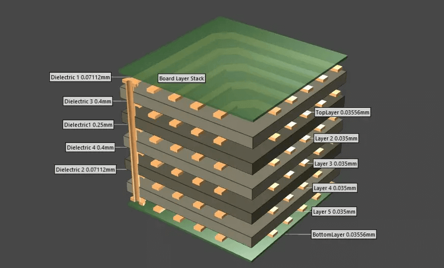
The distinction matters when reading a stackup drawing. Reinforcement built into the board, such as an additional layer of material inside a rigid-flex stack, is part of the construction and is defined by the fabricator. A stiffener is an external structure added to a specific area afterwards, and it is defined by the mechanical requirement.
Because the two are specified separately, they can also be reviewed separately. A rigid section inside the stack handles the overall shape of the product, while an attached stiffener handles the local load at one connector or one set of pads.
Materials and their properties
Polyimide stiffeners are the common choice for flexible circuits. They add support while retaining some bending capability, tolerate high-temperature processes, and remain light, which matters in handheld and wearable products where every gram counts.
FR-4 is the choice where rigidity is the requirement. It is a glass-fibre reinforced epoxy with high mechanical strength, low cost, and good heat resistance, and it is used widely on rigid-flex boards where the stiffened area has to behave like a rigid board.
Metal stiffeners serve applications that need more than stiffness. Stainless steel adds corrosion resistance and durability, aluminium is light and spreads heat effectively, and copper combines good conductivity with the ability to act as a shield against electromagnetic interference. A composite construction combining two materials is used where strength, weight, and cost have to be balanced against each other.

The stiffener material should be chosen from the load and the environment, not from what is already on the shelf. A stiffener that is too flexible does not protect the joint, and one that is too rigid can crack it.
The benefits, by category
Mechanically, a stiffener prevents the board from deforming where it must stay flat, improves durability in high-vibration environments, and supports connectors and densely packed components that would otherwise load the laminate directly. The result is a rigid local island inside an otherwise flexible circuit.
Electrically and thermally, metal stiffeners can spread heat in power-dense designs, while a stiffener also provides electrical isolation in high-frequency circuits and can reduce electromagnetic interference where a conductive material is used with a defined ground connection.
In manufacturing and assembly, the gain is reliability. A reinforced area reduces stress on solder joints during handling and reflow, and it makes the circuit easier to position and insert into an enclosure, which reduces the handling damage that flexible circuits are particularly exposed to.
Where stiffeners are used
Flexible and rigid-flex boards use them around connectors and vulnerable component areas, which is the most common application. Wearable electronics need very thin stiffeners, because the requirement is to add enough support for assembly without making the product uncomfortable to wear.
Automotive and aerospace assemblies use stiffeners where the board has to survive extreme environments and vibration, and medical equipment uses them to protect the reliability of imaging, diagnostic, and implantable devices, where a mechanical failure is not an option.
Design decisions
Material selection follows the application. The questions are how much flexibility must remain, how much strength is needed, how much heat the area will see, how much weight the product can carry, and whether heat has to be spread away from the region. The answers usually point to one material immediately.
Thickness and placement come next, and they are a balance rather than a maximum. A thicker stiffener is more rigid but less tolerant of the bend that continues around it, so the stiffener should cover the area that must stay flat and stop before the bend line that must remain flexible. Placement that ignores the bend line converts a flexible circuit into a rigid one with a stress concentration at the edge of the reinforcement.
Bonding is the third decision. Hot-melt adhesive suits high-temperature processes, a pressure sensitive adhesive suits automated placement because it requires only pressure to activate, and epoxy bonding provides a durable attachment where long-term stability is the priority.
Adhesive choice is a process decision as much as a mechanical one. The bond has to survive the assembly temperature, not only the operating environment.
Fixing methods and inspection
Most stiffeners are attached by hot-press lamination, which applies heat and pressure to bond the material to the circuit in one operation. Where the stiffener has to remain removable, mechanical fixing with screws or rivets is used instead, and the hole pattern then becomes part of the mechanical design.
Inspection covers both alignment and adhesion. Visual and dimensional checks confirm that the stiffener is in the right place and that the bond is complete, and the acceptance criteria are taken from the applicable IPC standard. For designs where the stiffener also carries a ground connection, that connection is verified electrically as well.
Two problems worth designing against
The first is warp and delamination, which appear when the material or the bonding process is mismatched to the circuit. Different expansion behaviour between the stiffener and the board is the usual cause, and the same issue is discussed for multilayer boards under PCB dimensional stability and expansion. Selecting materials with compatible behaviour and controlling the bonding cycle keeps it under control.
The second is the balance between weight and rigidity. Composite construction is the usual answer: combining polyimide with FR-4 or with a thin metal layer delivers the stiffness the area needs while removing the weight the product cannot carry. The mechanics that decide how the reinforced area meets the enclosure are covered under board outline and mounting design, and the adhesives used for bonding and sealing are described in our guide to potting and dispensing adhesives for PCBs.
FAQ
Does every flexible circuit need a stiffener? No. It is needed where a connector, a solder joint, or a dense component area has to remain flat, or where the circuit is inserted into a housing. A flexible circuit that never leaves a protected area may not need one.
Can a stiffener be added after assembly? It is better to plan it with the board, because the adhesive and the press cycle are part of the fabrication sequence. Adding one later risks the joints it is supposed to protect.
Does a metal stiffener always need a ground connection? Only if it is used as a shield or as part of the thermal path. A floating metal plate near a high-frequency circuit can couple rather than shield, so the connection is a design decision rather than a default.