
PCB Sample Board: What a Prototype Proves Before Volume
A PCB sample board is the first physical article of a design, and its purpose is to be wrong in a controlled way. Every assumption made during the layout, about a footprint, a clearance, a connector height or an impedance, becomes a measurable fact once the board exists. A sample run that is planned to test those assumptions is worth more than a larger run that simply reproduces them.
This article covers what a sample board should verify, how it differs from a prototype and a first article, and the checks that are worth building into the sample stage.
What a Sample Board Is For
The primary purpose is to answer questions that cannot be answered on paper. Does the footprint match the actual part? Does the connector engage the mating half at the right height? Does the fine-pitch device reflow without bridging? Does the impedance measure what the calculation predicted?
The secondary purpose is to prove the manufacturing process. A sample run tests the fabricator’s ability to hold the dimensions the design demands, and it tests the assembly process, the stencil and the reflow profile. Discovering on the sample that a 0.4 mm pitch device cannot be assembled with the current stencil is a cheap lesson; discovering it during volume production is not.

Sample, Prototype and First Article
The three terms are often used interchangeably and should not be. A sample board is usually a small quantity of the final design, made as a design verification step rather than as a demonstration. A prototype is a functional article used to demonstrate the product, and it may be deliberately built with a different process to save time. A first article is a production-representative unit, made with the final tooling and process, and inspected against the production documentation.
The distinction matters because the checks are different. A prototype answers whether the product works. A sample answers whether the design is correct. A first article answers whether the production line can make it correctly and repeatably. A project that skips the sample stage and goes straight to a prototype often discovers a footprint error at the worst possible moment, when the schedule has no slack left.
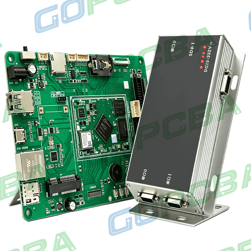
What to Verify Electrically
The electrical checks on a sample board go beyond powering it up. Continuity and isolation test on the bare board catches fabrication faults before components are placed. Impedance measurement on coupons or on test structures confirms that the stack-up produced the geometry that was designed.
Functional checks should be planned to isolate faults rather than to confirm success. Bring out test points on the power rails, on the clock and on the reset line, so that a board that does not start can be diagnosed without removing components. Provide options for injecting a clock or holding a device in reset, and include a way to measure the current on each rail separately. Debugging a first board is much faster when the design anticipated it. The rules in the prototype build requirements describe how to prepare the package so that the sample build runs without engineering queries.
What to Verify Mechanically
Mechanical verification is where the sample earns its cost. Connector heights, mounting hole positions, the clearance to the enclosure and the position of any component that has to protrude through a cutout are all difficult to check in a CAD model with confidence, and trivial to check with a physical part.
The sample should be fitted into the actual enclosure, or a representative model of it, with the actual mating connectors. A board that fits on screen and does not fit in the housing is one of the most common and most avoidable delays in a hardware project. Where the board carries an antenna, the keep-out must also be checked against the mechanical assembly, because a battery or a metal bracket placed inside the keep-out will degrade the radio even if the layout itself is correct.
Assembly Checks
The sample run also validates the assembly process. Paste volume, placement accuracy and the reflow profile can be examined on the first boards, and the stencil can be modified before the volume order. Design issues that only appear during assembly, such as a pad that is too small for a reliable fillet, or a component that shadows a neighbouring pad during placement, are visible at this stage and cheap to fix.
Following the placement and pad conventions described in the placement order and pad positioning guidance removes most of these problems in advance. Where they remain, the sample is the place to find them. It is also worth assembling one board by hand, deliberately, to confirm that every component can be reached with a soldering iron, because that will be necessary during debugging.
Panel Utilization and Cost
A sample order of a handful of boards is expensive per unit, because the setup is charged over a small quantity. The cost is dominated by the tooling and the panel, not by the number of boards, so increasing the quantity from five to twenty usually changes the price very little. Ordering enough for debugging, spares and a second assembly iteration is often cheaper than ordering twice.
Panel utilization affects the price as well. A small board that tiles many times on a standard panel amortises the setup over more units, and the design can help by keeping the outline within a standard panel dimension. The manufacturable design rules describe the outline and spacing conventions that achieve this.
Common Traps
The most common trap is treating the sample as a demonstration rather than as the design verification it should be. If the board works, the team moves on, and none of the assumptions are actually verified. Writing down the list of things the sample is supposed to prove, and measuring each one, converts a lucky success into knowledge.
The second trap is changing the design between the sample and the production order without re-running the sample. Any change to a footprint, a stack-up or a connector invalidates the verification that was done, and the change has to be re-checked on a new article. The third trap is omitting the impedance and stack coupons, which leaves the electrical assumptions unverified even while the product appears to work.
FAQ
How many sample boards should be ordered? Enough to cover assembly setup, debugging, destructive tests and spares. Ten to twenty is a common range, and the marginal cost of the additional boards is small compared with the setup charge. It is also worth ordering a few extra panels at the qualification stage, because the second assembly iteration normally reveals something the first one did not.
Should the sample use the production stack-up? Yes, if the purpose is to verify the design. A sample built on a different stack cannot confirm the impedance or the via performance, so any savings at the sample stage are paid back later as a redesign.
Can the sample double as the first article? Only if it is built with the production tooling and process and inspected against the production documentation. A board taken from a prototype run is not a first article, however similar it looks, because the process that produced it is not the process that will produce the volume order.