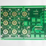
Air Conditioner PCB: Isolation, Relays and Inverter Drive
An air conditioner contains at least two boards that talk to each other, and between them they switch mains voltage, run a variable-speed compressor and read a handful of sensors. The result is a control design with an unusual combination of constraints: high voltage isolation on one side, millivolt-level sensing on the other, and a hostile thermal and humidity environment around both.
What the Board Controls
The main control board manages the compressor, the indoor and outdoor fans, the display and the communication link. On an inverter unit it also generates the variable-frequency drive for the compressor, which is what allows the system to modulate capacity instead of switching on and off.
Functionally the board performs four jobs. It reads temperature, humidity and pressure sensors, decides what the system should do, drives the power devices accordingly, and monitors for faults. It also handles protection: overcurrent, overtemperature, short circuit and loss of communication all have to result in a safe shutdown rather than a damaged compressor.
High Voltage Isolation and Creepage
The mains side and the control side must be separated by a barrier that withstands both the working voltage and any transient that arrives on the supply. That requirement governs the layout far more than the circuit does, because the distance between conductors, not the schematic, decides whether the board is safe.
creepage distance, measured along the surface, and clearance, measured through air, both have to be satisfied across the isolation barrier. Slots milled into the board are commonly used to increase the surface path without consuming layout area, and any component that straddles the barrier, such as an opto-isolator or a relay, must itself be rated for the working voltage.

Relays, Opto-Isolators and Their Drivers
Relays switch the higher-power loads that the inverter does not handle, such as the outdoor fan at fixed speed or a reversing valve. A low-voltage control signal cannot drive a relay coil directly, so a driver transistor or a small relay driver integrated circuit sits between the controller and the coil, with a flyback diode to absorb the energy stored in the winding when the relay releases.
An opto-isolator provides the signal path across the isolation barrier, and its placement is critical. The connector or isolator that spans the barrier defines where the barrier runs, so the layout is usually divided into a clean mains section and a clean low-voltage section with nothing else crossing the divider.
The Inverter Power Stage
Variable-speed compressors are driven by a three-phase inverter built from a power module or discrete switches, controlled by pulse width modulation. The stage draws significant current and generates both heat and switching noise, so it is placed at one edge of the board, close to the connector that feeds the compressor, with a heat sink mounted directly onto it.
The drive signals from the controller must be routed with attention to loop area and isolation, and the current sensing that closes the control loop must be positioned where it measures the motor current rather than something else. Poor placement of a shunt or a current transformer produces a control loop that oscillates or a protection circuit that trips at the wrong threshold.
Power Supply and Protection
The board needs its own low-voltage rails. A transformer with rectification and regulation, or a switching supply with an isolated topology, produces the logic supply, and a series regulator or additional converter supplies the gate drive. Surge protection at the mains input absorbs transients before they reach the semiconductor devices.
Protection is a design feature rather than an add-on. Fusing, metal oxide varistors, and a defined shutdown path for an overcurrent event all belong in the layout, and the fault signals they generate have to reach the controller across the isolation barrier without creating a new path for noise.
Operating Environment
Air conditioners work in humid, dusty and sometimes chemically aggressive environments. Condensation forms on cold surfaces when the unit cycles, and the outdoor board sees rain, salt air and insects. Component selection and layout both respond to that: sealed relays, conformal coated assemblies and generous spacing where the surface is exposed.
A conformal coating protects the surface but must be applied so that it does not trap contamination underneath it, and connectors and pressure-sensitive parts have to be masked. The coating is also a design decision, because it changes the thermal behaviour of the board and the creepage assumptions used at the isolation barrier.
Sensors and Signal Conditioning
Temperature sensing uses thermistors and resistive sensors, whose signals are small and slow. They need their own quiet ground reference and filtering close to the input, because the alternating currents of the inverter and the coil currents of the relays are both capable of corrupting a high-impedance measurement.
Placement follows the rule that applies to every mixed-signal board: keep the analogue section together, keep its ground return separate until the single reference point, and do not route a switching node underneath it. On a control board with a mains section eight millimetres away, that discipline is what keeps the measurements usable.
Fault Behaviour and Serviceability
Most field failures on these boards present as a fault code rather than as an obvious failure. Giving the controller enough measurement to distinguish between a sensor fault, an overcurrent event and a communication loss makes service possible without replacing the board, and the diagnostic information is usually what determines the repair cost.
Design for serviceability follows from that. Placing test points on the supply rails and the gate signals, keeping the fault indicators accessible and defining a clear board-level interface between the indoor and outdoor units all reduce the time a technician spends on diagnosis, which is usually the dominant cost of a repair.
Board Architecture and Layout Order
An air conditioner PCB is normally laid out in zones that follow the isolation boundary. The mains input and its protection sit at one edge, the inverter drive stage follows, the low-voltage control section occupies the middle, and the sensor and communication interfaces sit at the opposite edge. Nothing crosses the dividers except where the design intends it to.
Working in that order matters because the isolation barrier is fixed once the mains components are placed, and every later decision has to respect it. Sensors are sited on the quiet side, gate drive signals are routed with minimal loop area, and the current sensing that closes the inverter drive control loop is positioned where it measures motor current and nothing else. Keeping the switching nodes away from the sensing inputs follows the general EMI suppression design principles.
The last step is checking the creepage paths again after routing, since a via or a thin solder mask sliver placed near the barrier can reduce the effective distance that the initial layout was designed to achieve.
FAQ
Why are there several boards in one air conditioner? The indoor and outdoor units are physically separated and at different potentials of convenience, so each has its own control board, linked by a communication pair. Combining them would require running many more conductors through the interconnecting cable.
What usually kills one of these boards? Voltage surges on the mains, water ingress, and repeated thermal cycling of the power stage. Protection and sealing address the first two, and the third is managed by the thermal design of the inverter section.
Is a conformal coating worth the cost? In a humid environment it is usually the difference between a board that lasts and one that corrodes within a few seasons, provided the surface is clean before the coating is applied.