Audio PCB Design: Noise, Grounding, and Layout
Audio performance is one of the few specifications a customer notices immediately. A phone that sounds thin, an amplifier that hums, or a headset that clicks when a notification arrives are all failures of the board design as much as of the circuit. An audio PCB is built around signal purity, noise immunity, and electrical isolation, and those three priorities change how the layout is done.
What an audio PCB does
An audio PCB processes, amplifies, or converts an audio signal. It appears in power amplifiers, digital-to-analog converters, soundbars, wireless earbuds, and automotive multimedia systems, and in every one of those cases the requirement is the same: deliver the signal without adding anything to it.
The core components
An operational amplifier provides gain and filtering in the analog signal path, and its placement relative to the supply and to the input connector often decides the noise floor of the whole product. Capacitors and resistors set the signal flow, block direct current between stages, and shape the frequency response, and their tolerance is audible in filters and in tone control networks.
Digital audio components such as converters, signal processors, and microcontrollers handle the data path rather than the analog signal. Supply filtering and regulation complete the chain by providing a clean, stable rail, which is the part most often underestimated: an audio circuit cannot be quieter than its supply.

Layout and isolation decide the result as much as the parts list. A good operational amplifier on a poor layout sounds worse than an ordinary one on a careful layout.
Types of audio board
Analog audio boards process continuous signals and suit amplifiers and powered speakers. Digital audio boards process discrete data and appear in wireless earbuds, USB audio interfaces, and streaming products. Mixed designs combine both, and the boundary between them is where the design work concentrates.
Layer count follows the requirement. A single-layer board is inexpensive and adequate for simple circuits, while four and six layer boards provide the isolation and thermal performance that higher-end products need. Rigid, flexible, and rigid-flex constructions serve different mechanical constraints, with flexible and rigid-flex boards common in true wireless earbuds and wearable speakers where space is measured in millimetres.
Where audio boards are used
Consumer products account for the largest volume: phones, wireless earbuds, televisions, and speaker systems. Professional audio comes next, covering mixing consoles, recording interfaces, preamplifiers, and equalizers, where the noise requirement is far stricter because the signal may be amplified many times over.
Automotive audio uses the same boards for head units, active noise cancellation, and multichannel amplifier control, in an environment that adds vibration and temperature cycling to the electrical requirement. Industrial voice systems, including alarms, public address equipment, and announcement systems, complete the list, with reliability and intelligibility as the priorities rather than fidelity.
Design fundamentals
Noise isolation is the first principle, and it is achieved with a continuous ground plane, shielding where a sensitive node is exposed, and a clean physical division between the analog and digital areas of the board. The same separation should exist on the schematic, so that the two returns meet at one deliberate point rather than everywhere. The reasoning behind that arrangement is set out in our guide to mixed-signal PCB design guidelines.
Impedance matching is the second principle, and it matters wherever a signal leaves one stage and enters another, because a mismatch produces reflection and, in an audio path, audible distortion. Component placement is the third: a high-gain stage placed next to a switching supply will amplify the supply noise along with the signal, and no amount of filtering at the output removes it.
Material choice is the fourth and usually the simplest. Standard FR-4 satisfies most audio designs, while high-fidelity and radio-linked products may justify a low-loss laminate. The threshold is the frequency content and the required noise floor, not the price of the product.
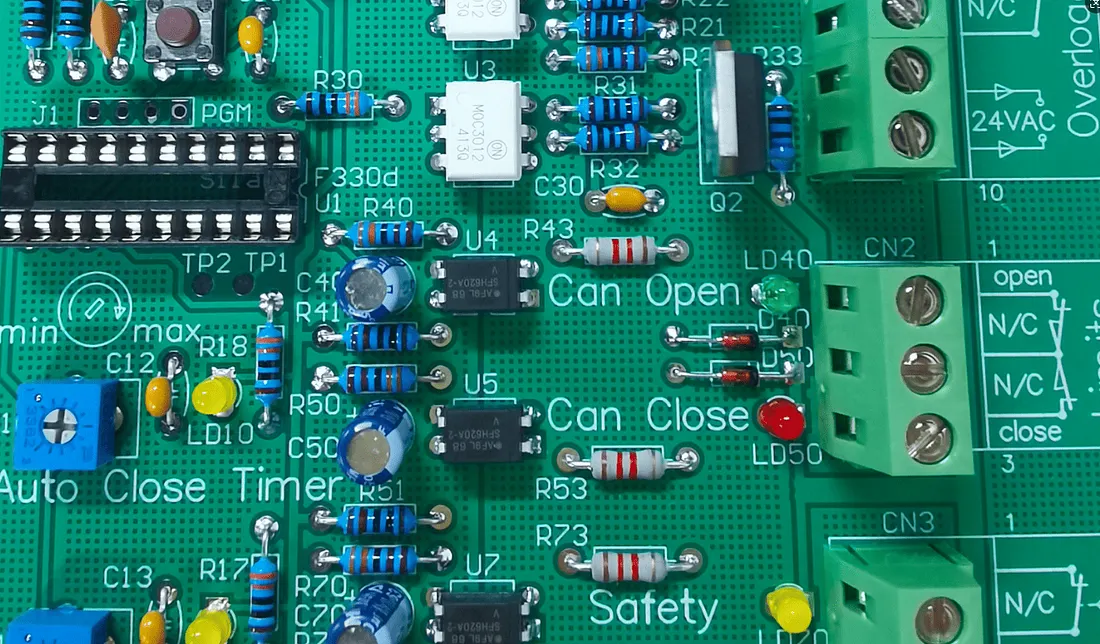
Every audio complaint maps to a physical path. Hum comes from the supply and the ground, clicks come from switching events, and hiss comes from gain applied to a noise floor.
The symptoms to design against
A mains-frequency hum is a grounding and supply problem, and it is solved by controlling the return path rather than by adding components. A click or pop is a switching event, either in a power supply or when a digital stage changes state, and it is addressed by keeping those transitions away from the analog path.
Hiss is a gain structure problem: the signal is too small relative to the noise floor of the first stage. And a low-frequency buzz often traces back to harmonic content on the ground rather than to a fault in the signal path, which is the behaviour described in our guide to ground current and harmonic distortion. The practical geometry of these returns is covered in ground routing and power trace planning.
Cost structure
A single-layer analog board with common parts sits at the low end of the range. A double-layer board built around an operational amplifier stage costs more, and a four-layer mixed analog and digital design costs more again because of the additional lamination and the tighter layout discipline it requires.
A six-layer board for a high-end DAC occupies the top of the ordinary range, and a rigid-flex audio board for true wireless earbuds sits above it, because the mechanical construction adds process steps that a rigid board does not have. Volume then works in the usual direction: a production order reduces the unit price substantially compared with a prototype, which is dominated by tooling and setup.
Choosing a manufacturer
Four capabilities matter for audio work. Experience with audio circuits is the first, because the failure modes are specific and familiar to a shop that has seen them before. Support for mixed-signal and impedance-controlled routing is the second, and the ability to build multilayer and rigid-flex constructions is the third for compact products. Prototype capability with short turnaround is the fourth, since audio designs are usually tuned by measurement and iteration rather than finalised on paper.
Where the digital section belongs
The converter is the boundary. Everything upstream of it is digital and can be treated as such, with its own ground return and its own supply filtering, while everything downstream is analog and needs the quiet conditions described above. Treating a DAC as a digital component because it accepts a digital input is the mistake that produces a noisy output stage, because the device has both a digital interface and an analog output, and the two reference systems meet underneath it. That is why the converter belongs on the boundary between the regions rather than inside either one.
FAQ
Can an ordinary circuit board be used for audio? Yes, but it will be more susceptible to noise and distortion. An audio layout concentrates on grounding, isolation, and placement in ways a general-purpose board does not.
Which material is best for audio? Standard FR-4 is sufficient for most products. Low-loss laminates are justified when the design has high-frequency content or a very demanding noise target.
Is audio design suitable for a beginner? A basic analog board is a reasonable first project. Once converters, digital signal processing, or mixed layouts are involved, the layout discipline becomes the hard part rather than the circuit.