Video Recorder PCB: Design for High Speed Video Capture
A video recorder board is a small system that happens to be shaped like a circuit board. It has to capture a high bandwidth data stream from an image sensor or a video decoder, process it, buffer it, write it to storage and deliver power to all of that inside a housing with no airflow. Video recorder PCB design is the work of keeping four demanding interfaces from interfering with each other.
What the Board Carries
The input side receives a video stream, either from an image sensor over a serial interface or from an external source through a decoder chip. The stream is usually multi-lane and always fast, which makes it the highest performance net on the board and the one that sets the stackup.
The processing side carries the application processor, its memory bus and the power delivery network that feeds it. The output side carries the storage interface, whether a card socket, a flash array or a network connection, and the user interface. Each of those blocks has its own timing and its own noise signature, and they share one board.
The Capture Interface
A serial image or video interface runs as one or more differential lanes with an embedded clock, and each lane is a controlled impedance pair that has to be length matched both within the pair and across lanes. Any skew between lanes reduces the sampling window at the receiver, and any asymmetry converts differential signal into common mode noise that couples into everything nearby.
The routing rules are therefore strict. Keep the lanes on a single layer if possible, give them a continuous reference plane, and avoid vias unless the layer change is unavoidable. Keep the pair spacing constant through bends and avoid tight serpentines that change the coupling along the run, as described in serpentine routing and length matching.
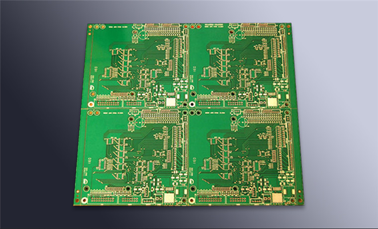
Memory and Storage Interfaces
Memory interfaces are wide, fast and sensitive to length matching across the whole bus. They also consume a large share of the board area, because the address and data lines fan out from the processor to the memory device and each has to be tuned so that all signals arrive within the same timing window. Placing the memory close to the processor is the most effective single decision available.
The storage interface is usually slower but not trivial, and it often sits at the board edge where a connector or card socket is mounted. Its routing should not be allowed to cross the high speed capture lanes, and its return path should be continuous, since a card interface typically carries several signals switching simultaneously. Escapes from a dense processor to memory are covered in blind and buried via stack selection.
Power Delivery and Noise
The processor runs from several rails at low voltage, and each of them has a transient requirement that the regulator alone cannot meet. The decoupling network, the plane arrangement and the placement of the capacitors as close to the pins as possible together determine whether the rails stay inside their tolerance when the processor changes state.
A video pipeline is particularly demanding because the load changes in step with the frame rate rather than continuously, so the current steps are large and periodic. That makes the low frequency part of the decoupling network important as well as the high frequency part, and it makes the regulator layout, including its switching loop and its feedback path, directly relevant to the picture quality, following the approach in ground routing and power trace planning.
Thermal Management in a Sealed Case
Recorders are commonly enclosed in a sealed or fanless housing, which means heat has to leave through the enclosure surface. The processor is the largest contributor, followed by the storage device and the power conversion stage, and the sensor adds its own contribution on the input board.
The thermal path is built from copper: a spreader area under the processor, thermal vias into the internal ground planes, and a defined contact to the housing through a thermal pad or a metal boss. Where the board has to stay sealed, the internal air is the only medium for the components that are not directly coupled to the case, so the spreader area and the plane copper have to be generous.
Layout Priorities
Place the processor and its memory first, closest to the thermal interface and with the shortest possible interconnect between them. Then place the capture interface connector and the sensor so that the lanes run directly without crossing other signals. Then place the power conversion away from the sensitive analog input and the clock circuitry.
Route the highest speed interfaces before anything else, in the order of their data rate, and keep the slower control and monitoring nets for last. The service and firmware interface, the status indicators and the power sequencing signals can be routed around the critical nets rather than through them, and doing so avoids most of the rework that a mixed high speed design otherwise attracts.
Stackup and Interface Planning
The stackup is chosen from the fastest high speed interface on the board, and everything else is arranged around it. If the capture lanes need a controlled impedance over a specific dielectric thickness, that constraint fixes the layers adjacent to the signal layers and therefore the plane arrangement for the processor rails as well.
It is worth mapping every interface on a single sheet before layout begins, with its rate, its length limit and its reference plane requirement. Most of the routing conflicts in a recorder design are visible on that sheet, and resolving them there costs a few hours instead of a revision of the artwork.
Protection and Environmental Considerations
Recorders are frequently used outdoors or in vehicles, so the board has to survive moisture, temperature cycling and vibration. A coating on the finished assembly protects the conductors from condensation and contamination, and the choice of material has to be compatible with the connectors and with any test points that must remain accessible.
Connector retention matters as much as the coating. A card socket or a video connector that is held only by its solder joints will eventually crack under vibration, so mechanical reinforcement or an additional fixing point is normally designed in. The environmental protection options are described in conformal coating and board protection.
FAQ
How many layers does a video recorder board need? Usually six to ten. The count is driven by the need for a continuous reference plane under the capture lanes and the memory bus, plus the separate planes required by the processor supply rails.
Can the storage device share a supply with the processor? It can, but the switching current of the storage interface produces noise on the rail that the processor is also using. Separate rails or at least separate filtering between the two are worth the small component cost.
Does the board need a low loss laminate? It depends on the lane rate and the trace length. Multi-gigabit lanes over a short run work on a standard laminate, while longer runs or higher rates benefit from a lower loss material, and the decision should follow a loss budget calculation.