Robot Vision System PCB: Design and Function Guide
Machine vision looks simple from the outside: a camera sees a part, software decides what it is, the robot moves. Inside the camera and on the board behind it, a large amount of data moves very quickly, and the design decisions that make it work are the ones a robot vision system PCB has to solve. The sensor produces far more data than the processor can consume serially, the interface between them must be treated as a transmission line, and the whole assembly frequently has to fit inside a sealed enclosure on a moving arm.
What the Board Has to Do
The image sensor is the starting point, and it is a high speed digital device with a parallel or serial output rather than an analogue one. The board must deliver clean power to it, provide a low jitter clock, carry its output to the processor with controlled impedance, and keep the noise of the processor out of the sensor supply. Any error in that chain appears as fixed pattern noise, as a dropped frame or as a line of corrupt pixels.
Beyond the capture path, the board handles illumination control, triggering, the interface to the robot controller and often the first stage of image processing. In a smart camera all of that sits on one board; in a distributed system it is split between a sensor head and a processing box connected by a cable, which moves the problem to the interface.
Sensor Interface and High Speed Routing
Modern sensors use a serial differential interface with a clock lane and several data lanes, and the board design follows the same rules as any other high speed link. Each lane is a differential pair with a specified impedance, the pairs must be length matched to each other so that the data arrives together, and the ground plane beneath them must be continuous. A pair that crosses a plane split is the classic cause of a link that works on the bench and fails at temperature.
The clock has its own requirement: low jitter. The clock should be routed away from switching supplies, kept short, and where the sensor can generate its clock internally or accept one from the processor, the choice should be made deliberately rather than by default. Where the distance between the sensor and the processor is significant, a serialiser can be used to move the data over a single pair, which trades latency for simplicity and greatly reduces the number of traces that must be matched. Our blind and buried via article describes the high density routing techniques that follow.
Latency and Determinism
In a robot the image is used to decide a movement, so latency is not only a performance figure but a control loop parameter. Every part of the chain contributes: the exposure time, the readout, the transfer, the processing and the interface to the controller. The board contributes the transfer and the interface, and it also determines whether the latency is consistent, which matters more than the absolute value because a control loop can be tuned for a delay but not for an unpredictable one.
Determinism is largely a matter of avoiding shared resources. A data path that competes for the same memory bandwidth as the processor’s other work will occasionally be delayed, and the resulting jitter shows up as a variable response in the robot. Designing the memory architecture so the capture path has its own bandwidth, and using a hardware interface rather than a software one for the trigger, are the usual remedies.
Power, Grounding and Thermal Design
A vision board combines an extremely sensitive analogue front end, a fast digital core and often a high current illumination driver on the same piece of laminate. The illumination driver is usually the largest load and the most disruptive, so it is placed at the opposite end of the board from the sensor, with its own filtering and its own return path to the supply.
Thermal design follows the enclosure. A camera in a sealed housing on a robot arm has almost no airflow, and the processor and the illumination driver must conduct their heat into the housing rather than into the air inside it. Thermal vias beneath the processor, a copper area on the reverse of the board and a mechanical path to the housing are the standard measures, and the assumptions must be based on the internal ambient. Our thermal management article describes how that estimate is made.
Mechanical and Environmental Considerations
The board usually lives on a moving structure, so vibration and cable flexing are real loads. Connectors take the brunt of it, and a connector that relies on its solder joints alone will fail; the standard practice is to fix the cable near the connector so that the joint carries no load, and to select connectors with a positive retention feature.
Environmental protection is often achieved by the enclosure, but the board can help. Conformal coating protects against moisture and contamination and also damps vibration slightly. Where the camera is used in a washdown environment, the coating has to cover the whole assembly including the connector interfaces, and the coating must be compatible with the connector’s own sealing arrangement rather than fighting it.
Test and Validation
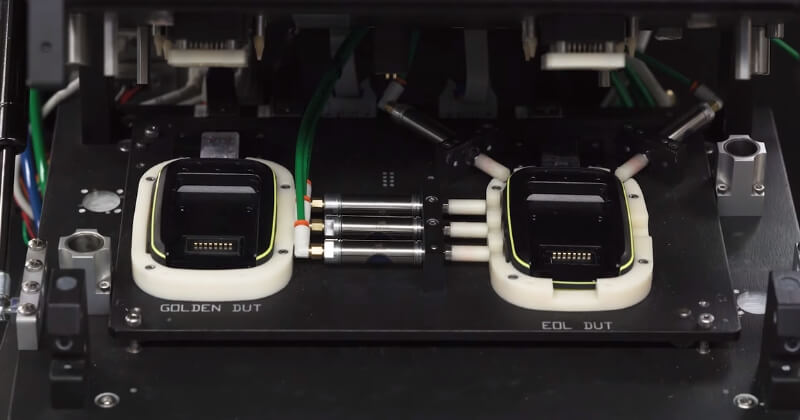
Functional test covers the sensor link, the illumination, the trigger and the host interface, and it should be performed with a representative image rather than a static pattern, because some link errors only appear when the data changes. Eye diagrams on the high speed lanes are useful during development, and a bit error rate measurement at temperature is the most convincing evidence that the link is sound.
The test that catches the most problems is the thermal one: run the camera at full frame rate with the illuminator active until the temperature stabilises, then verify that the image quality and the link both remain within specification. A design that passes at room temperature and fails when warm is almost always a timing margin problem on the sensor interface or a supply that was not derated for the internal ambient. Our design release checklist places those checks in the review sequence.
Interfaces, Cabling and System Integration
The stack itself is simple: a base plate, a dielectric and one copper layer. The cost is dominated by the base, which is priced by weight and by the process used to prepare its surface, and by the dielectric, whose thickness and thermal performance are the two variables that most affect the price. A thicker dielectric costs less to make but performs worse thermally, so a design that specifies a thin high performance dielectric should be clear about why it needs one.
Where the product needs connections between layers, the construction becomes a multilayer metal core board and the cost rises sharply. Two dielectric layers, two copper layers and a lamination step that must bond to metal without warping are all inherently more expensive than the single sided version. Sizing the copper generously on one layer is usually cheaper than adding a second one, which is why so many successful metal base designs are single sided.
FAQ
How long can the cable between the sensor head and the processor be? It depends entirely on the interface and the data rate. A serialiser allows several metres over a controlled impedance cable, while a direct parallel interface is limited to a few centimetres on the board.
Is impedance control really necessary for an image sensor link? Yes, at the data rates used by modern sensors the traces behave as transmission lines. Without controlled impedance and length matching, the data eye closes and the link becomes marginal at temperature.
Why does image quality degrade as the camera warms up? Usually because the sensor supply has drifted or because the link timing margin has shrunk. Both are traceable to a design that did not account for the internal ambient of the enclosure.