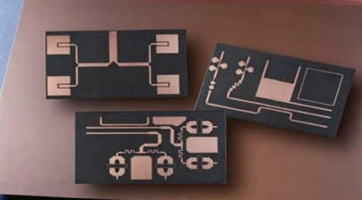
LNA RF Module PCB Design: Noise Figure and Grounding
A low noise amplifier sits at the front of a receive chain and carries an unusual burden. Everything downstream adds noise on top of the noise it contributes, and the gain it provides cannot recover signal to noise ratio that has already been lost. The LNA RF module therefore has to be built so that the first stage adds as little noise as the device physics allows, and the board is a large part of that.
Why the Board Sets the Noise Floor
An amplifier datasheet quotes a noise figure measured in a reference fixture with an ideal match. In a real module, the loss between the antenna and the device input appears directly in the system noise figure, because a passive loss ahead of a gain stage adds its own noise without adding gain.
That is why even a fraction of a decibel of extra insertion loss in the input line is worth arguing about. A short, wide, well referenced trace with a solid ground beneath it is not a cosmetic preference; it is the difference between meeting a sensitivity target and missing it.
Impedance Matching at the Input
The input match has to present the source impedance the device was characterised against, and that match is normally built from discrete components rather than from a quarter wave line, because the module has to be small. At the frequencies involved, the parasitic inductance of a via or the capacitance of a pad is a significant fraction of the matching element.
Correcting those parasitics is part of the design rather than a refinement. A matching network calculated on ideal components and placed on a real board will land somewhere else, so the layout should be modelled with the pad and via parasitics included, and the matching elements should be placed with a ground via immediately at each shunt node.

Ground Plane Continuity
The ground plane under an LNA is a reference, not a convenience. Every radio frequency line needs an unbroken plane directly beneath it, because a gap forces the return current to detour, which adds inductance, changes the impedance and radiates. A plane split under the input line can cost a decibel or more on its own.
Stitching vias along the edges of a coplanar structure keep the top and bottom grounds at the same potential and suppress the parallel plate modes that would otherwise travel between them. A spacing of a fraction of a wavelength is the classic rule, and in practice designers place them much closer, at two to three times the substrate thickness.
Via Parasitics and Component Selection
A via is an inductor. Its inductance depends on length and barrel diameter, and at a few gigahertz that parasitic can dominate a matching network designed on paper. Shunt elements need a short, wide connection to ground with via arrays rather than single holes, and the same applies to the device ground pad.
Components themselves have to be chosen for the band. A capacitor that looks like a capacitor at a hundred megahertz can be inductive at five gigahertz, so self resonance is part of the selection. Resistors used in bias networks should be the thin film type if their noise contribution matters, which it does when they sit in the input path.
Bias Network and Decoupling
The supply to a low noise device has to be quiet without being slow. Decoupling close to the bias point keeps the radio frequency out of the supply line, and a series resistor or inductor isolates it further, but every element added to the bias path also contributes thermal noise if it is placed where the signal can see it.
The usual solution separates the two concerns. Radio frequency chokes and bypass capacitors are placed at the bias node, while a clean regulator and additional filtering sit further away. Where a long bias line is unavoidable, a shielded trace or a stripline run between planes keeps it from coupling into the input.

Shielding and Isolation
An LNA has high gain and a low level input, which makes it an excellent detector of its own output. If any of the amplified signal couples back to the input, the amplifier will oscillate or at least show a lumpy response. Layout separation, a via fence between input and output, and a shield can over the stage all reduce that risk.
Isolation also has to consider the rest of the module. A transmitter or a digital section on the same board radiates into the input unless it is separated and screened. The reasoning follows the general principles in EMI suppression design principles, applied at a much lower signal level than usual.
Transmission Line Choice
Microstrip is the easiest line to route and leaves the top side accessible for matching components, which is why it dominates small RF modules. Grounded coplanar waveguide adds a top side ground and a low inductance return right at the pad, which suits shunt elements and screened circuits, at the cost of tighter geometry control.
Stripline is fully shielded but buries the line inside the board, so components cannot be attached to it directly. The comparison and the design equations for each are set out in microstrip and stripline routing.
Assembly Effects on Performance
Solder volume changes parasitics. A joint with more paste than intended moves the component slightly and changes the pad capacitance, which shifts a match that was tuned on the bench. On a small module with a narrow band, that shift can be enough to move the centre frequency outside the requirement.
Voiding under the device ground pad is equally important, because voids raise the source inductance and reduce gain. Filling and capping the thermal vias gives a flat surface for the joint, and the relevant structures are described in via in pad or plated through.
Test and Verification
Noise figure cannot be measured with ordinary bench equipment. It needs a noise figure analyser or a calibrated gain and noise method, with the reference plane set at the module connector, and the measurement has to be repeated at the temperature extremes the product will see.
Small signal measurements of gain and return loss on a network analyser come first, since they show whether the match is right, and the noise measurement confirms the result. Recording both per unit rather than per batch is what makes a production process controllable, because it exposes drift before it becomes a yield problem.
FAQ
Does the laminate need to be PTFE for an LNA? Not always. Where the loss budget permits, a low loss hydrocarbon material performs well. PTFE is reserved for cases where every tenth of a decibel counts.
How important is the ground plane really? It is usually the single largest layout contribution to performance. An unbroken reference under the input line is worth more than any component upgrade.
Can the matching network be tuned after assembly? Partly. Trimming elements is possible, but the parasitics that shifted the match in the first place are not removed by tuning, so the layout should be correct before the first build. If the match has to be tuned, the change should be recorded against the board revision, since the same adjustment will be needed on every unit built to that revision.