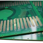
PCB Area Estimation: How to Size a Board Before Layout
The cheapest moment to change a board size is before layout starts. Once the outline, the connectors and the mounting holes are fixed, the enclosure and the mechanical parts are committed as well, and a late realisation that the circuit will not fit becomes an expensive redesign. PCB area estimation is the discipline of getting that number approximately right from the netlist and the bill of materials.
Why a Rough Estimate Beats No Estimate
An estimate made at concept stage is always approximate, and that is acceptable. Its purpose is to answer a structural question: does this design need a 50 mm square board or a 100 mm square board? Getting that within twenty percent is enough to size the enclosure, choose a connector and decide the layer count.
The alternative, waiting until layout is complete to discover the size, usually means the mechanical design has to change after tooling has been ordered. A few hours of estimation early is far cheaper than that.
Component Area Factors
Start with the bill of materials and assign each part an area that includes not only its body but the room it needs around it. A small passive such as an 0402 resistor occupies roughly 2 to 3 mm² of board area once its pads, courtyard and a share of the routing space are counted. A 0603 part is slightly larger, and a small outline transistor package takes a similar area.
Integrated circuits scale with pin count rather than body size. A package with 48 leads needs considerably more space than its outline suggests, because the escape routing around it consumes area on every side. As a working figure, allow between 1 and 2 mm² per pin for a fine pitch device, plus the decoupling capacitors that sit beside it.

Routing Channels and the Layer Budget
Area is consumed by conductors as well as by components. Estimate the number of connections that must cross each region of the board, divide by the number of traces that fit side by side at the chosen width and spacing, and compare the result with the width of the channel available. The routing channels include the reference plane, and both compete for the same area.
If the estimate shows that the required channels exceed the available width, the options are more layers, finer geometry or a larger board. Making that choice at concept stage is easy; making it after the enclosure is tooled is not.
Connectors, Mounting and Keep-Outs
Connectors are the most underestimated item on any board. A connector needs the space for its body, room for the mating plug to travel, and clearance for the cable to bend. A board-to-board connector needs both halves to align, which fixes the position of one connector relative to the other with little freedom.
Add the mounting holes with their keep-out rings, the board edge margin required by the fabricator and the panel, and any area reserved for a shield can or an antenna keep-out. On radio products the antenna clearance can be the single largest consumer of board area, and it is invisible in a component count. Mechanical constraints of this kind are collected in the notes on board outline and mounting design.
<img src="https://www.gopcba.com/wp-content/uploads/2024/09/Turnkey_PCB_Assembly.webp" alt="Component placement floorplan with keep out zones marked” />
Thermal and Test Requirements
Power components need copper area, not just footprint. A switching regulator may require a copper pour several times its own area to spread heat, and a motor driver may need a thermal via field into an internal plane. That copper has to be counted as occupied space even though nothing is mounted on it.
Test points consume area too. A design with full in circuit test access needs a probe pad on every net, spaced so that a fixture can reach them. Where test access is provided only at the edges or through a connector, the requirement is smaller, but the decision should be made deliberately rather than inherited.
Typical Densities by Product Class
Useful reference points make the estimate more reliable. A consumer product with a dense layout may reach 8 to 12 components per square centimetre, an industrial controller with wider spacing and higher voltage clearances typically sits between 4 and 8, and a power conversion board with large magnetic components sits lower still.
Fine pitch digital designs change the picture because the packages are large and the routing is dense, even though the component count is low. Estimating by component count alone underestimates these boards, which is why the pin based figure matters.
Checking With a Floorplan
Once the estimate is made, sketch a floorplan. Place the connectors, the mounting holes and the large components at their approximate positions and see whether the remaining area can accommodate the rest. A floorplan takes less than an hour and reveals conflicts that a spreadsheet cannot, such as a connector that blocks the only plausible route to the power stage.
The exercise also exposes the mechanical interfaces early. If a display must sit in a particular place, or a sensor must be isolated from a heat source, those constraints belong in the floorplan before any detailed routing begins. The placement order and pad positioning described in placement order and pad positioning are the natural next step.
When the Estimate Is Wrong
Estimates fail in both directions. A board that turns out much smaller than predicted usually means the component areas were overestimated, and the design can be shrunk, which reduces cost. A board that does not fit is the more common problem, and the recovery options are limited once the mechanical design is fixed.
Keeping a small reserve from the start is the practical answer. Allowing twenty percent more area than the estimate requires costs a little material and gives the layout room to absorb the connections that always appear late. Boards designed to the last square millimetre usually need a revision before they are manufacturable, and that revision costs more than the reserve would have.
Component Density as a Design Yardstick
Component density is the simplest way to compare a proposed design with one that already exists. Count the placed parts, divide by the estimated board area, and compare the result with a board of a similar class that has been built and tested. The comparison is rough, but it catches an estimate that is off by a factor rather than by a percentage.
A density figure also predicts the layer count. Below roughly five components per square centimetre, a two layer board is usually sufficient. Between five and ten, four layers become common. Above ten, six or more layers are typical, because the routing channels rather than the parts themselves drive the requirement.
Record the figure for each project. After a few products, the numbers from previous designs become the most reliable estimating tool available, and they cost nothing to collect. The layout discipline that follows from a realistic density target is described in the notes on manufacturable design guidelines.
FAQ
How accurate should the estimate be? Within about twenty percent is enough to size an enclosure and choose connectors. The purpose is a structural decision, not a final dimension.
Should the estimate include a reserve? Yes. Allow twenty percent or so above the calculated requirement, because late additions to a design are normal and the routing always needs more room than the netlist suggests.
What drives area most on a modern board? Usually the connectors, the mechanical keep-outs and the copper needed for thermal performance rather than the component count itself.