Projector PCB: Architecture, Types and Design Considerations
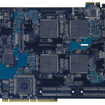
A projector packs a display engine, a bright light source, a video pipeline and a power supply into a box small enough to sit on a table. The electronics have to drive the light source with precise timing, move video data at high rates, control cooling that keeps the optics in tolerance and do all of it without radiated noise reaching the imaging path. A projector PCB sits at the centre of those competing requirements.
What the Main Board Does
The main board accepts video from several possible sources, decodes it, scales it to the panel resolution and formats it for the display device. Alongside that pipeline it controls the light source, manages the cooling system, reads temperature and position sensors and communicates with the user interface.
Those functions have very different electrical characters. A video pipeline is a set of high speed differential links; the light source driver is a power converter; the sensors are slow analogue signals. Keeping them from interfering with each other is the main architectural decision on the board.
Signal Chain and Video Interfaces
Modern interfaces arrive as differential pairs at several gigabits per second, which means controlled impedance, matched lengths and a continuous reference plane. The traces are short in a compact product, but short and badly referenced is worse than long and properly referenced, because a return path discontinuity creates jitter that no equaliser can remove.
Signal integrity work starts at the connector and continues through any multiplexer or switch to the processing device. Each transition costs something, so the component count in the high speed path is kept low, and every interface is routed as a single controlled unit rather than as a collection of individual nets.
Light Source Drivers
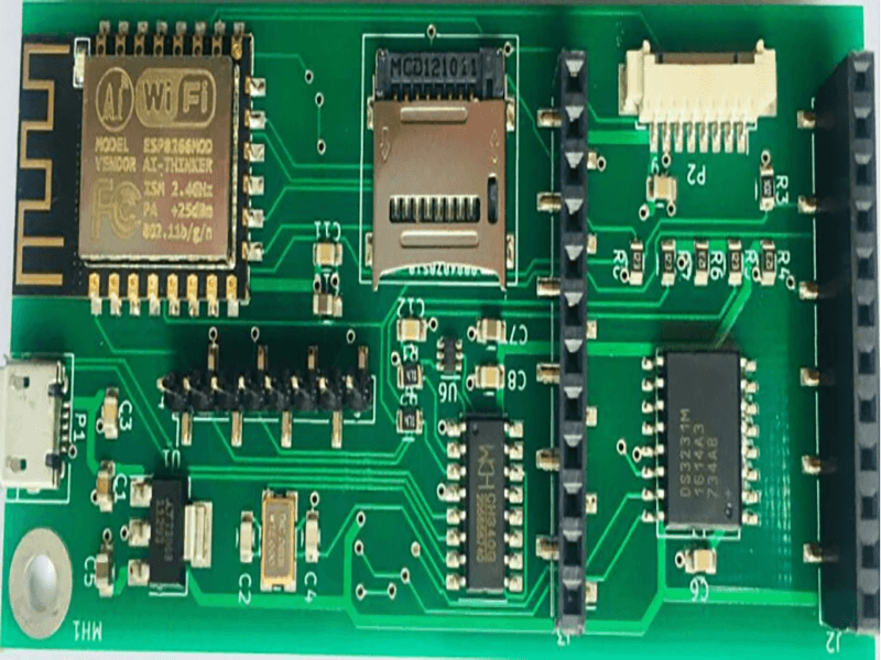
A lamp based projector needs an igniter and a ballast, while an LED or laser projector needs constant current LED driver channels with tight current matching so that the colour balance does not shift as the output changes. In both cases the driver is a switching converter placed near the light source and controlled from the main board.
These stages carry substantial current and switch at frequencies that can couple into the imaging path. Layout discipline matters more than component choice: a tight switching loop, a solid return under the converter, and physical distance or a ground barrier between the driver and the video section do most of the work.
<img src="https://www.gopcba.com/wp-content/uploads/2026/01/2.png" alt="Thermal management structure on a projector main board” />
Thermal Management Inside a Small Box
A projector generates heat in the light source, in the display device and in the electronics, all inside an enclosure that is acoustically damped and therefore poorly ventilated. The thermal design is a system problem, and the board participates in it by spreading heat and by conducting it to the air stream.
Copper area under the display device and the processing chip, thermal vias into a plane, and a mounting arrangement that presses the board against a heat sink or a chassis wall are the available tools. Fan control is part of the same loop: the fan speed is set from temperature measurements, which means the sensor placement determines whether the loop is stable or oscillates.
Noise Control and the Imaging Path
The display device is sensitive to electrical noise, and the board contains several switching converters and a digital pipeline. Colour artefacts, banding and dropped frames can all originate in the power distribution rather than in the processing.
Separating the supplies is the first measure. The display device receives a filtered rail from an analogue regulator rather than from the main converter, the ground reference under it is continuous, and the high speed video lines do not cross the split between digital and analogue regions. The partitioning approach is the one described in mixed signal PCB design guidelines.
Boards in Different Projector Types
A compact LED projector has a small board with an integrated power stage and a modest display device, often with the driver and the processor on the same layer stack. Its constraints are size and cost, and the thermal load is relatively low.
A large venue projector with a high power lamp or laser source separates the functions. The ballast or laser driver becomes its own board mounted next to the light source, the main board carries the video processing, and the two communicate through a defined interface. Splitting the boards keeps the switching noise away from the imaging electronics and simplifies cooling, at the cost of additional connectors and harnesses.
Layout Rules That Matter
High speed differential pairs are routed first, with their reference plane kept intact and any layer changes accompanied by return vias. Power converters are then placed so that their switching loops are short and their fields do not reach the video section or the display device.
Analogue sensing lines, such as thermistor inputs or position feedback, are filtered and routed away from switching nodes, with their return to the analogue ground reference. Sizing the power conductors follows the usual current calculation, described in trace width and current calculation, since a voltage drop on a lamp or laser supply line changes the light output.
Assembly and Mechanical Considerations
An optical system demands mechanical precision, and the board often defines the mounting datum for the display device and the optics. Board flatness therefore becomes an optical parameter: a warped board tilts the display device and shifts the image.
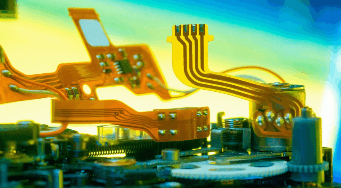
Controlling flatness means a symmetric stackup, sensible copper balance and a panel support arrangement that holds the board flat through reflow, and the reasoning behind that balance is the same as for any high layer count design of the kind described in multilayer PCB advantages for high speed. Where the display device is mounted on a separate substrate and connected by a flexible cable, the interface between the two becomes the critical dimension, and the connector placement should be defined early.
Test and Verification
Electrical test verifies the board, and functional test verifies the image. A test pattern is projected and analysed for uniformity, colour accuracy and stuck pixels, which catches faults that continuity testing cannot see, such as a marginal display interface or a noisy supply.
Thermal testing under load is equally important, because a projector that meets its specifications when cold and drifts after twenty minutes has a thermal design problem rather than a signal problem. Measuring the temperature of the display device and the main processor at full brightness gives the numbers needed to close that loop, and the measurement should be repeated with the enclosure closed, because a board that runs cool on an open bench is not evidence of anything in a sealed product.
FAQ
How many layers does a projector main board need? Six to ten layers is typical, driven by the number of high speed interfaces and the need for separate power and ground planes. Compact LED models can work with four.
Why does image quality change after warm up? Usually thermal drift in the optics or a timing change in the display interface as the driver temperature rises. Both are addressed by thermal design rather than by signal tuning.
Can the power supply share the main board? It can where the output is modest, but the noise and thermal penalties usually favour a separate supply board, particularly above a hundred watts.