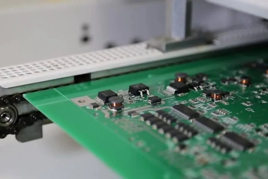
Refrigerator PCB: Control Board Design and Reliability
A modern refrigerator contains more electronics than its mechanical parts suggest. The compressor runs from a variable frequency drive, the fans are speed controlled, the defrost cycle is scheduled by a microcontroller and the temperature is measured in several places at once. The refrigerator PCB that ties those functions together has to work for fifteen years in a damp, cold and occasionally very hot environment.
What the Control Board Does
The main board reads temperature sensors from the fridge and freezer compartments, controls the compressor drive and the evaporator fan, operates the defrost heater and the damper, and manages the user interface and the display. Some designs split this between a power board and a display board connected by a harness.
The functional split matters less than the environmental one. The board sits at the back or the bottom of the appliance where condensation forms, where the mains supply is present and where the compressor produces both electrical noise and vibration.
The Inverter Compressor Drive
Modern compressors use a brushless motor driven by an inverter, which converts the mains supply into a variable frequency three phase output. The drive stage includes a rectifier, a power factor correction stage in better designs, a direct current bus with a large capacitor bank and a three phase bridge.
Electrically this is the hardest part of the board. The bus voltage is high, the switching currents are large and the loop from the bridge to the motor has to be short to keep the emissions down. Sizing the conductors is a current and temperature calculation of the kind described in trace width and current calculation, and the bus capacitor placement decides how much of the switching current circulates in the board rather than in the cable.

Sensor Inputs and Analogue Accuracy
Temperature is measured with thermistors or with digital sensors on a bus. A thermistor input is a resistive divider against a reference, and its accuracy depends on the reference and on the analogue to digital converter as much as on the sensor itself.
The sensor cables run through the appliance, next to the compressor wiring, and they pick up noise. Input filtering, a stable reference and a return path that does not share the motor current are what keep the measurement meaningful. Where several sensors share a connector, the returns should be brought back separately rather than merged at the connector, since a shared return turns the cable resistance into a temperature error.

Relays, Triacs and Load Switching
Defrost heaters, dampers, lights and solenoid valves are switched by relays, triacs or motor driver outputs depending on the load. Each of them produces a transient when it switches, and the transients couple into the supply and into the sensor wiring.
Switching devices belong together on one part of the board, away from the analogue inputs, with their own return path to the supply. Snubber networks or varistors across inductive loads reduce the transient at the source, which is always preferable to filtering it out after it has spread through the board. The general techniques for keeping a switching stage quiet are described in low cost signal quality improvements.
Power Supply and Surge Withstand
An appliance board takes its power from the mains, so it has to survive surges, fast transients and the voltage dips that occur when a compressor starts. A fuse and a varistor at the input, followed by an input filter and a switching supply, is the usual arrangement.
The layout of the input protection matters as much as the parts. The varistor should be placed at the connector so that the surge is clamped before it travels across the board, and the creepage and clearance distances between the mains side and the low voltage side have to be maintained across the whole isolation barrier, including around slots and under components. Surge protection that is 20 millimetres away from the entry point still lets the transient reach the rest of the board.
Humidity and Condensation
Condensation is the dominant environmental threat to an appliance board. The board is cold when the appliance is off and warm when it runs, and the cycle draws moisture onto surfaces. Once moisture sits on a board with a dirty surface and a voltage difference, electrochemical migration begins.
A conformal coating is the standard countermeasure, and it has to cover the sensitive areas without coating connectors and test points. Avoiding tight conductor spacing, keeping the surface clean and choosing a coating that resists the cleaning agents used on appliances are all part of the same decision, as described in conformal coating and board protection.
Thermal Behaviour
Refrigeration electronics run cool for most of their life, but the compressor compartment can be hot, especially at the back of the appliance where the condenser rejects heat. The board has to tolerate that environment while also dissipating the losses of its own power stage.
Copper area on the power devices, thermal vias into a plane and a mounting position that allows some conduction into the chassis all help. Electrolytic capacitors are the components most sensitive to temperature, and their position and the local temperature set the service life of the whole board, so keeping them away from the hottest area is worth some layout effort.
Vibration and Mechanical Considerations
The compressor transmits vibration into the chassis, and the board is usually mounted on plastic standoffs that do not damp it well. Large and heavy components such as electrolytic capacitors and relays need mechanical support, either through a clip, a bead of adhesive or a shape in the enclosure that holds them.
Board support during assembly matters for the same reason. A large appliance board can flex during handling, and flexing a board with surface mount parts on it cracks joints. Supporting the board under the placement area and handling it by the edges prevents most of that damage.
Test and Reliability Verification
Production test covers the obvious functions and the safety related ones. An insulation resistance test between the mains side and the low voltage side is standard, along with a functional test of the compressor drive and the sensor inputs, and a check of the relay outputs.
Validation runs the board through the environmental extremes, including humidity with bias, thermal cycling between the appliance off state and the compressor compartment temperature, and the mains disturbance tests that apply to the market. Recording the results against the board revision is what makes the evidence useful later, since a component change can invalidate the conclusion as easily as a layout change.
FAQ
Why does the board fail after a few years? Usually contamination combined with humidity, or an electrolytic capacitor aged by temperature. Both are design decisions rather than random failures.
Can the display and power stages share a board? They can, but the mains isolation distances and the display’s exposure to touch make a split arrangement easier to design and to certify.
Is a coating always needed? In a damp appliance environment it is normal practice, and it is one of the cheapest reliability measures available. The specification should name the material, the thickness and the areas to be masked, and the coverage should be verified on a production sample rather than assumed from the process settings.