Flexible Circuit Board Types: Single, Double, Multilayer, Rigid-Flex
Most design guides treat flexible circuits as one category, which is why so many first attempts pick the wrong construction. In practice there are four families, and the cost, the layer count, and the assembly difficulty rise sharply as you move up. Knowing which family a product belongs to before layout starts saves more money than any amount of routing optimization afterwards.
Single-Sided Flex
Single-sided flex is the cheapest of the flexible circuit board types, and it should be the default choice when the electrical requirements are modest and everything can be routed on one layer. A single-sided flex has one etched conductive pattern on one side of the insulating film, usually rolled copper on polyimide. Commercial products use it constantly, from the ink cartridge in a printer to the memory module inside a computer.
The film is not limited to polyimide. Polyester, aramid paper, and PVC all appear in single-sided constructions where the temperature and flexibility demands are lower. What matters is that the choice is made deliberately, because the film determines the maximum soldering temperature and the number of bend cycles the part will survive.
Double-Sided Flex
A double-sided flex carries an etched pattern on both faces of the film and connects them with plated through holes, so the two sides form a continuous conductive path while the part still bends. This is the point at which the design stops being a printed pattern and starts being a circuit board, because the vias add a mechanical feature that does not bend. Coverlay protects the conductors on both sides and marks where components are placed.
The vias also define where the circuit cannot bend. A plated hole in a thin film is a rigid inclusion, so the bend zone has to be planned around it. Flexible circuits with vias in the middle of a dynamic bend area fail at the via, not at the conductor, which is a failure that shows up only after the product is in the field.

Multilayer Flex
A multilayer flex laminates three or more single or double-sided circuits together and forms plated through holes across the whole stack. The advantage is routing density without complex soldering: a design that would need dozens of wires and connectors can be built as one laminated part. The layer count is technically unlimited, but flexibility is not, which is why assembly dimensions, layer count, and bend requirements have to be traded against each other rather than optimized separately.
The general rules for how layers stack and how they should be ordered apply here as well, and they are summarized in layer stackup from one to eight layers. As a rule, keep the flexing region to the minimum number of layers the routing allows, and move the remaining layers into the rigid sections.
Rigid-Flex Construction
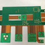
A rigid-flex board laminates rigid and flexible substrates together selectively, joining the sections with plated through holes so that the finished part is one continuous structure. Because reliability and cost both track layer count, the manufacturer will normally try to keep the number of layers as low as the design permits, and the designer should cooperate by moving anything that does not have to be in the flex region into a rigid section.
The structure is tight and mechanically stable, which is why it appears in products that have to survive vibration and thermal cycling. The place where it normally goes wrong is the transition between the rigid and flexible areas; the plated holes and the conductor exits have to be arranged so that the bend does not start at a rigid inclusion. Layer-specific design rules for those transitions are covered in blind and buried via stack selection.
HDI Rigid-Flex and Where It Fits
The high-density-interconnect version of rigid-flex adds microvias, finer lines, and thinner dielectrics to the same structure. HDI rigid-flex combines the routing density of an HDI board with the mechanical architecture of a rigid-flex part, which is what allows a design to put a high pin count device on a rigid island and still fold the assembly into a small enclosure.
It is the most expensive option of the four, and it is used where nothing else fits: aerospace instruments, medical devices, and dense consumer products. The reason is not only density but repeatability. Once the stack is qualified, the same part can be produced with consistent impedance and consistent geometry, which matters more in a product built in the hundreds of thousands than in a prototype.

Design Rules Common to All Four
Whatever family a design belongs to, the same few rules decide whether the part works. Keep conductors perpendicular to the bend line, radius every internal corner, and leave a defined margin between the conductor and the cut edge so that trimming and handling have material to spare. Keep the flexible region as thin as the routing allows, because every added layer reduces the bend radius the part can tolerate and makes the neutral axis harder to control.
Vias are the other common thread. A plated hole is a rigid inclusion in a film, so each family places them with more care as the layer count rises. In single-sided flex there are none. In double-sided and multilayer flex they should sit outside the bend zone, ideally on the stiff side of the neutral axis. In rigid-flex and HDI rigid-flex they belong in the rigid sections wherever possible, with the transition arranged so that the bend starts in uniform film rather than at a plated feature.
How to Choose
Work from the motion requirement outward. If the circuit does not move and only has to fit a shape, a single-sided flex with a stiffener is usually enough. If it moves once during assembly, a double-sided flex handles the routing. If it must survive repeated cycles, reduce layers in the bend, use rolled copper, and consider moving the rigid content into a rigid-flex structure. The full sequence from layout to volume production is described in PCBA development process.
Cost follows the same ladder, and it is worth stating plainly. A single-sided flex is priced close to a rigid board of the same area, a double-sided flex adds plating and a second coverlay, and each additional layer multiplies the lamination and drilling steps. Rigid-flex adds a second material system and a bonding operation between them, and HDI rigid-flex adds microvia formation and finer registration on top of that. A design that can be satisfied one step lower on the ladder should be, because the difference is not a few percent; it is often a factor of two or more at volume. The question to ask is not which construction is best in the abstract, but which is the lowest step that still meets the bend requirement, the routing density, and the reliability target for the product.
FAQ
Is a multilayer flex always better than a rigid-flex board? No. Multilayer flex is cheaper when the whole assembly can bend, but once a significant part of the circuit needs component support and tight tolerance, moving that content into a rigid section is usually smaller and more reliable.
What limits the number of bend cycles? The copper, the film, and the geometry. Rolled copper, a large bend radius relative to thickness, and fewer layers in the flexing zone all raise the number of cycles the part survives.
Where do flexible circuits usually fail? At rigid inclusions such as plated vias, at sharp internal corners, and at the transition between a rigid and a flexible section, not in the middle of a straight conductor run.
Can a single-sided flex use polyimide? Yes, and it usually should when the part sees soldering temperatures. Polyester and PVC are cheaper but limit the thermal exposure the part can take.