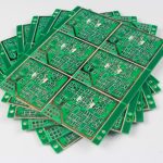
Industrial Control Board Layout Standards
An industrial control board is judged on three things: the chipset it is built around, the way the layout and the routing have been handled, and the quality of the parts and the laminate. Of those three, the layout is the one a buyer can assess only indirectly, and it is the one that decides whether the controller runs for a decade or resets every time a contactor closes.
This article looks at the layout and routing decisions that distinguish a control board built for a machine cabinet from a board built for a desk, and at the routing techniques that are often applied badly.
What an Industrial Control Board Has to Survive
The environment is the first difference. A control board sits in a cabinet with a power supply, contactors, motor drives and relays, and it has to operate over a wide temperature range while tolerating vibration and a supply that is neither quiet nor clean. The enclosure is often the only airflow, and the wiring to the board may be several metres long in each direction, which turns every cable into an antenna and every field terminal into a point where a transient can enter.
The second difference is service life. A consumer product may be replaced within a few years; an industrial controller is expected to remain in service for a decade or more, and in many cases to be repairable. That changes the design priorities: long-term reliability and the ability to diagnose a fault matter more than the last few percent of cost, and a board that is difficult to service is a liability for the whole life of the machine it controls.

Layout Constraints That Come From the Chassis
Connector positions on a control board are usually fixed by the enclosure. Expansion slots, field wiring terminals, indicator positions and the aperture in the cabinet panel all determine where a connector has to sit, and those positions cannot be rearranged for the convenience of the routing. This means the placement exercise starts with the mechanical constraints and works inward, rather than starting from the logical grouping of the circuit.
Where the mechanical arrangement is fixed, the design freedom that remains is in the copper between the connectors and the devices. Field wiring terminals should be arranged so that the high-current and the signal connections arrive on separate edges where possible, and the return path for the switching currents should be kept away from the signal ground of the processor. These are the layout decisions that the cabinet cannot make.
The Processor, the Chipset and the Memory
The connection between the processor, the memory controller and the memory devices is the most sensitive part of the board. The controller and memory vendors publish design guidelines for exactly this region, and following them is the cheapest way to obtain a working design: the guidelines contain the routing lengths, the layer assignment and the decoupling requirements that the part was characterised with.
Departing from the reference arrangement is possible, but it should be a deliberate decision with simulated or measured evidence rather than a cost-saving measure. A reference design generally carries more margin, more layers, or more components than strictly necessary, and trimming it is a legitimate engineering exercise provided that what was removed is understood and its effect assessed.
Serpentine Routing and Length Matching
Serpentine routing exists to add length in a controlled way. The clock lines between a memory controller and its memory devices have to arrive within a defined skew of each other, and where two traces on the same layer cannot be made the same length by direct routing, one of them is detoured so that the total lengths match.
The quality of the match matters more than the appearance of the pattern. A serpentine whose segments are too close together couples to itself, and the coupled sections change the impedance of the trace, which is the opposite of what the length adjustment was meant to achieve. The spacing between adjacent segments should be at least three times the trace width, the amplitude should be kept as small as the routing allows, and the serpentine should sit over an unbroken reference plane for its whole length.
Why More Serpentine Is Not Better
A common mistake is to treat the presence of serpentine routing as evidence of a sophisticated design. The pattern is a compensation for a length mismatch, not a feature. Where a layout has a great deal of it, the more interesting question is why the components are arranged so that so much length has to be added.
Dense serpentine also makes the copper distribution uneven. A region packed with meandering traces has a different copper density from the region next to it, and that difference affects the lamination, the impedance and the etching. A board whose routing density is uneven across its area is harder to fabricate consistently, and the rules for serpentine length matching include keeping the density variation within a reasonable band. The question of whether a trace is a microstrip or a stripline also depends on this, because the length adjustment changes which layer the signal is referenced to.

Power, Copper Balance and Thermal Design
A control board usually carries several rails, often derived from a single industrial supply, and each converter generates heat as well as noise. Placing the converters away from the processor and from any analogue input is the first step, and giving each one a compact local loop with its input capacitor and return path is the second.
Copper balance is the quieter requirement. Heavy copper on one side of the board and little on the other produces a panel that distorts during lamination and a board that behaves differently when it warms up. Thermal design follows from the same thinking: the heat has to be spread through copper and moved to the enclosure or the airflow, and a design that concentrates all the dissipation in one corner will have a hot spot regardless of how good the components are.
Materials, Layer Count and Manufacturability
Industrial boards typically use a laminate with a higher glass transition temperature than a consumer board, because the cabinet temperature in summer may be well above the ambient the design was specified at. The layer count is driven by the routing requirements of the processor and memory interface rather than by the number of nets, and a board that needs six layers for the memory interface will not become a four-layer board by tightening the rules.
Manufacturability deserves a mention because of the copper weights involved. Thick copper, heavy current traces and a wide temperature range together make the process window narrower, and the design rules that keep a board manufacturable are worth reviewing before the layout is frozen rather than after the first fabrication quotation comes back. Good component placement, sensible routing and a stack-up that the fabricator builds routinely are what allow a control board to be both reliable and affordable.
FAQ
Should a control board follow the chipset reference design? Yes, for the processor and memory region, because the vendor guidelines describe the arrangement the part was characterised with. Departures should be based on evidence rather than on cost alone.
How much serpentine routing is acceptable? As little as the length matching requires. A layout with a great deal of it usually indicates a placement that could be improved, and dense serpentine also creates uneven copper distribution.
What laminate should an industrial board use? One with a glass transition temperature comfortably above the maximum cabinet temperature, and one the fabricator processes routinely. The reliability benefit of a higher grade material is real, but only if the process is controlled for it.