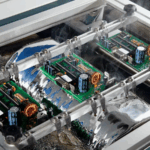
Via Plugging: Tenting, Filling and Process Choice
Once a board carries surface mount devices, the vias stop being a detail and become an assembly requirement. A hole that is open, or that traps solder, produces a defect that shows up as a short or a void rather than as a broken connection, and the fix has to be built into the process rather than inspected afterwards. Via plugging exists to close that gap, and the choice of method determines whether the result is a flat pad or a hidden cavity.
What Via Plugging Is For
Five problems are addressed by closing the vias. The first is solder wicking: during wave soldering, solder can travel through a via and appear on the component side, where it bridges adjacent features. The second is flux residue, which lodges inside an open hole and is difficult to remove completely. The third is the vacuum used during in-circuit test, which is formed more reliably when the surface is not perforated. The fourth is paste loss, where solder paste flows into an open hole and leaves a starved joint. The fifth is solder ball ejection during wave soldering, where trapped material escapes from the hole and lands elsewhere on the board; the alternatives are compared in via in pad or plated through.
A via in pad, where the hole sits inside a component land, is where the requirement becomes strict. The via must be plugged first and then plated or finished, so that the land presents a continuous surface for the device. This is the case where the result has to be flat, and flatness is the property that separates the various processes from one another.
Three Levels of Requirement
Not every design needs the same result, and specifying more than the design needs is expensive. At the loosest level, copper in the hole is sufficient and the via may be tented with mask or left open; tenting alone is enough when nothing sits over the hole. At the middle level, the hole must contain solder with a specified thickness, must not admit mask ink, and must not contain a trapped solder ball. At the strictest level, the via must be covered by mask ink so that no light passes through, must be free of solder rings and solder balls, and must be flat.
The middle level exists for a specific reason: if mask ink enters a hole that should be solder-filled, the ink prevents the solder from wetting the barrel and the joint becomes unreliable. The strict level exists for boards where every via has to look and behave the same, which is typical of dense assemblies with fine-pitch devices on the same surface. A tolerance of plus or minus 1 mil on the surface of a plugged via is a reasonable target at that level, with no reddening or tinning at the via rim, and the geometry it has to fit is set by via design rules.
<img src="https://www.gopcba.com/wp-content/uploads/2026/08/low-loss-PCB-laminate-material.png" alt="Via plugging and solder mask coverage on a dense PCB surface” />
Plugging After Hot Air Leveling
The simplest sequence applies the mask, levels the surface with hot air, plugs the vias that require it, and cures. Because the board has already been levelled, the plugging step cannot cause the mask to lift at the via rim, and this is the main advantage of the order. The plug ink is usually the same as the surface ink or a photosensitive or thermally cured alternative.
Its limitation is the surface. Plugging after levelling tends to contaminate the surrounding area and to leave an uneven surface, which is exactly the condition that causes a starved or voided joint on a fine-pitch device. The result is usually acceptable for boards without devices over the vias, and usually unacceptable for boards with them.
Plugging Before Leveling, With Planarization
Moving the plugging step earlier gives better flatness but demands more from the plating line. One route plugs the vias, cures, grinds the surface flat, and then transfers the pattern: pre-treatment, plugging, grinding, pattern transfer, etching, and finally surface mask. Because the plug is ground level before anything else is printed, the vias end up flat and the subsequent levelling does not cause blistering or ink loss at the rim.
The cost is copper. The barrel has to reach its final thickness in a single plating step, which puts a heavy demand on the plating process, and the grinding has to remove the resin completely from the copper surface without contaminating it. Shops that lack a one-pass heavy copper capability or a capable grinding line cannot run this route, which is why it is less common than its results would suggest.
Plugging Before Leveling Without Planarization
A middle route plugs the vias through a stencil and then prints the surface mask directly, with only a short wait between the two operations. The sequence is pre-treatment, plugging, screen printing the mask, pre-bake, exposure, development, and cure, and the mask has to be printed within about half an hour of plugging, so the two steps behave as one.
The result is good coverage, flat plugs, and consistent wet-film color, and after levelling the vias do not take solder and do not hide solder balls. The difficulty is control. Ink from the plug can climb onto a pad during cure and degrade solderability, and the solder mask at the via rim can blister or lift after levelling. Holding the process inside its window takes specific parameters, which makes this route productive in a shop that has tuned it and risky in one that has not.
A variant plugs, cures, and pre-cures before grinding and printing the surface mask: plug, pre-bake, development, pre-cure, then surface mask. It does prevent ink loss and blistering after levelling, but it does not fully solve trapped solder balls or tinning at the via, so customers whose requirement is the strict level usually reject it.

Plugging and Surface Mask in One Pass
The shortest route does both jobs at once. A screen of suitable mesh count is mounted, a backing plate or pin bed supports the panel, and the same print that applies the surface mask also closes the vias. The sequence is then pre-treatment, print, pre-bake, exposure, development, and cure, with no separate plugging operation at all.
Its advantages are time and equipment utilization, since one pass replaces two, and it reliably prevents ink loss at the via and tinning after levelling. Its weakness is air. A screen print drives ink into a hole that still contains air, and during cure that air expands, ruptures the mask film, and leaves a cavity that is neither flat nor fully closed. Levelling then finds a few vias that still take solder.
This is a parameters problem rather than a fundamental one. Adjusting the ink type and its viscosity, and setting the printing pressure for the panel, is what removes the voids and restores flatness, and once the recipe is established the route is stable enough for volume production. It is the most economical option when the requirement is the strict level and the process is under control.
Choosing Between Them
The decision follows the requirement and the shop. If the design has no devices over vias, the simplest route, plugging after levelling, is adequate and cheapest. If the requirement is the strict level with flat plugs and no solder balls, the choice narrows to the planarized route and the single-pass route. The planarized route produces the best geometry but needs a heavy copper capability and a capable grinding line, and it is closely related to electroplating and via filling in HDI. The single-pass route is faster and undemanding on equipment, and depends entirely on a tuned ink and printing recipe. The remaining variant, plugging and curing with grinding before the surface mask, sits between them and satisfies neither extreme, which is why customers with a real requirement tend to reject it.
What matters most is that the level is stated. The shop cannot tell from the artwork which of the three a design needs, and the cheapest process that satisfies an unstated requirement is rarely the one the designer had in mind.
FAQ
Which level should I specify? The strict level if any via sits under a component land or the board carries fine-pitch devices. Otherwise the middle level is usually sufficient and less expensive.
Why does a plugged via sometimes still take solder? Because the plug was not complete. Air trapped in the hole expands during cure and ruptures the mask, leaving a cavity that levelling can still fill.
What does planarization buy? A flat surface. Grinding the cured plug level before the pattern is printed produces a via coplanar with the pad, which is exactly what a land over a via requires.
Why must the surface mask be printed soon after plugging? Because the plug ink has to still be in a state that bonds to the mask. Leave it too long and the two layers do not adhere, which shows up as lifting at the via rim after levelling.