PCB Material Requirements: Copper Clad Laminate Selection
Material selection is one of the few decisions on a circuit board that is difficult to reverse later. Changing the laminate after the design is released means changing impedance targets, thermal behaviour and often the fabrication process itself. Understanding what a copper clad laminate actually is, and how the available grades differ, makes the choice a deliberate one rather than a default.
What Actually Determines the Material Choice
The governing factor is the product, not the board. A design produced to satisfy a formal order uses the material that order specifies, and that specification usually comes from the product requirement rather than from the circuit. Where the product demands high frequency performance, thermal endurance or flexibility, the material follows from it.
Absent such a requirement, most designs default to a general purpose glass reinforced epoxy. That default is reasonable, but it should be a conscious choice, because the material determines electrical behaviour, mechanical strength, moisture absorption, thermal limits and cost at the same time.
How a Copper Clad Laminate Is Built
A copper clad laminate, sometimes written as two words, is a composite of three things: a substrate, copper foil and the adhesive system that bonds them. The substrate is itself a composite, formed from a polymer resin reinforced with a fibrous material, which is what gives the sheet its mechanical strength and its dimensional stability.
The copper foil is bonded to one or both faces. Foil of around 35 micrometres is the common starting point, corresponding to the familiar one ounce weight, and thinner or heavier foils are available depending on the current and impedance the design requires. A sheet clad on one face gives a single-sided board; clad on both faces it gives a double-sided board, and the bond strength is provided by the adhesive chemistry rather than by the copper itself. Common finished thicknesses are around 1.0, 1.5 and 2.0 millimetres.
Common Substrate Types and Their Designations
Laminates are classified in several ways at once. By reinforcement they divide into paper base, woven glass cloth and synthetic fibre. By resin they divide into phenolic, epoxy, polyester and polytetrafluoroethylene, among others. By application they divide into general purpose and special purpose grades.
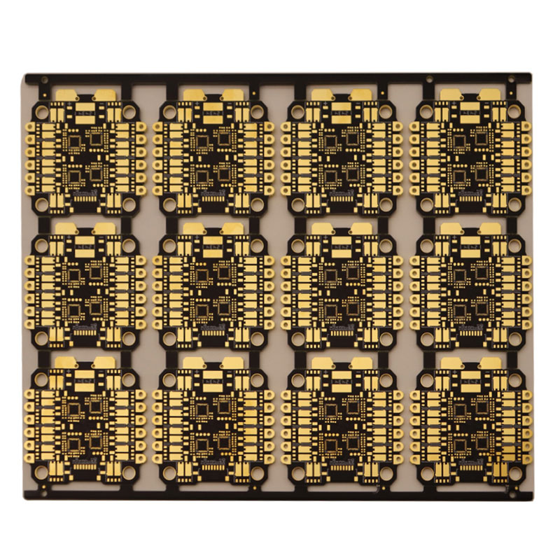
The familiar designations encode these differences. FR-4 is woven glass with epoxy resin and remains the workhorse of the industry. FR-1 and FR-2 are phenolic cotton paper grades, with FR-1 the more economical. FR-3 combines cotton paper with epoxy, while FR-5 uses glass with epoxy at a higher thermal grade and FR-6 uses matte glass with polyester. The CEM family spans composite constructions, CEM-1 and CEM-3 being the most widely used. Beyond that lie specialist materials such as aluminium nitride and silicon carbide for thermal work. Standard grades and their limits are compared in FR-4 versus G-10 laminate.
Resin chemistry determines the extremes. Polyester and polyimide appear where flexibility or severe thermal endurance is required, with polyimide being the material of choice for boards that must survive extreme temperature cycling or that form part of a flexible construction. A polyimide board costs substantially more than an epoxy equivalent and is harder to process, so it is specified where the thermal or mechanical requirement genuinely demands it rather than as a precaution.
Thermal Grades and the Glass Transition
Within a given chemistry, the most consequential variable is the glass transition temperature of the resin system. Below that temperature the material behaves as a rigid glass; above it, the resin softens, the coefficient of thermal expansion rises sharply and the mechanical properties deteriorate. A board that operates near or above its glass transition will suffer at every subsequent process step.
This is why laminates are offered in normal, middle and high glass transition grades, and why lead-free assembly pushed demand toward the higher ones. Multiple reflow passes at lead-free temperatures expose the board to more thermal stress than the older tin-lead processes did, and a standard grade may survive one pass comfortably while struggling with three. Assembly thermal load is therefore part of the material decision, not a downstream detail. The relationship between resin and reinforcement is described in prepreg versus core.
High Frequency and RF Materials
Radio frequency work imposes a different set of requirements. Compared with a general purpose laminate, an RF design prefers a substrate with a low dielectric constant and a high quality factor, because a lower dielectric constant reduces the distributed capacitance of a transmission line, raises its impedance and shortens the delay for a given physical length.
Specialised high frequency materials address this directly, and they also offer tighter control over the dielectric constant from batch to batch, which matters because impedance depends on it. The trade is cost and, frequently, more demanding processing. Where a design mixes RF with other circuitry, the choice of material is often the first structural decision, because it constrains how the two sections can be laid out together. Material properties and their effect on impedance are covered under PCB dielectric constant.
Mixed RF, Digital and Low Frequency Design
Modern radio equipment often carries RF, intermediate frequency and low frequency monitoring circuitry on the same board, sometimes even within the same outdoor unit. Preventing these sections from interfering with one another places demands on the material and on the layout at the same time.

The usual approach treats the RF section as a separate board electrically, even when it shares the same laminate. That means single-sided or double-sided construction for the RF area to minimise distributed parameter effects, a shielding cavity where possible, and a clear division between the RF and digital regions. Ground via fences and a shield can between the sections suppress coupling, and crosstalk control within the digital area follows standard practice: controlled impedance with matched termination, spacing based on simulation rather than habit, and blind or buried vias where additional routing area is needed. Stacking traces directly above one another on adjacent layers is best avoided, since that coupling is stronger than between neighbours on the same layer.
Writing Material Requirements into an Order
A material specification should name the laminate family and, where it matters, the specific grade; state the finished board thickness and the copper weight on each layer; and record any thermal or electrical requirement that follows from the product, such as a minimum glass transition temperature or a target dielectric constant tolerance.
Surface finish and colour belong in the same note, as do any special requirements such as a flexible or rigid-flex construction. Where a small sample quantity is being ordered, the price is normally driven by layer count, material and surface finish rather than by area, so stating the requirements precisely at the outset avoids a quotation built on the wrong assumptions. For high frequency designs the criteria are set out in the notes on dielectric constant.
FAQ
Is FR-4 always the right default? For general purpose digital and analogue boards it usually is, because it is well understood, widely available and inexpensive. Above roughly a few gigahertz, or where thermal load is high, a more specialised material is normally justified.
Why does the glass transition temperature matter so much? Above it the resin softens and expands faster, so the board distorts more during soldering and is more likely to suffer barrel cracking or delamination. Multiple lead-free reflow passes make the margin important.
Why do RF boards use a different substrate? A low dielectric constant and low loss reduce distributed capacitance and signal loss at high frequency. That improves impedance control and reduces attenuation compared with a general purpose laminate.