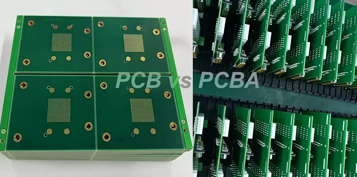
IoT PCB Copper Thickness: Choosing 0.5 oz or 2 oz
Copper thickness is the parameter that quietly sets how much current a board can carry, how well it sheds heat and how much it costs, and on a small IoT board it is decided almost by accident. The designer chooses the layer count and the laminate, the fabricator builds what the drawing says, and the copper weight is often left at the default. On a battery powered IoT PCB that is usually correct, and on a gateway with a radio and a motor driver it is not.
Why Copper Weight Matters More on a Small Board
Copper on a board does two jobs: it carries current and it spreads heat. Both become harder as the board gets smaller. A narrow trace on a dense layout has a higher resistance than the same trace on a larger board, the voltage drop across it rises, and the heat it produces has less area to escape from. The same product constraints that make an IoT board attractive, its small size and its sealed enclosure, also make thermal management difficult.
Battery powered products add a second pressure. Any voltage lost in the wiring is energy that does not reach the load, and on a device expected to run for years on a single cell the difference is measurable. Choosing a heavier copper layer purely for the supply and ground can be worth more than a change of regulator.
What the Ounce Ratings Mean
Copper weight is quoted in ounces per square foot, which is a weight rather than a thickness, though for practical purposes half an ounce is about seventeen micrometres, one ounce about thirty five, two ounces about seventy and four ounces about one hundred and forty. Most consumer and IoT boards are built with one ounce outer layers, and the industry standard stackup for a four layer board often pairs a half ounce or one ounce inner layer with one ounce outer layers.
The outer and inner layers do not have to match. Using a heavier copper on the layers that carry power and a lighter copper on the layers that carry signals is a common compromise, and it is cheaper than making the whole board heavy. The constraint is that the fabricator must be able to laminate and etch the combination, which is a question to ask before the stackup is frozen.
Current, Resistance and Voltage Drop
The current carrying capacity of a trace is not a single number. It depends on the copper weight, the trace width, the permitted temperature rise and the position of the trace in the stack, because an outer layer dissipates heat more easily than an inner one. Charts derived from the IPC standards give the width needed for a given current and temperature rise, and they should be used with the actual copper weight rather than with a default assumption.
Resistance and voltage drop follow from the same geometry. A trace sized to carry the current without overheating may still drop more voltage than the circuit can tolerate, particularly on a low voltage rail, so the two checks have to be done separately. The relationship between width, copper weight, current and temperature rise is set out in trace width and current calculation.
Heat Spreading and Thermal Vias
Copper is also the board thermal conductor, and a heavier layer spreads heat from a hot component over a wider area before it has to cross the laminate. That is why power converters and motor drivers are usually built on two ounce or heavier copper even when the current could be carried by narrower traces. The copper plane becomes part of the heat sink.
Thermal vias connect the heat spreading copper on the surface to copper on other layers and to any metal structure behind the board. Their effectiveness depends on the copper they connect to as much as on their number, and a via array under a thermal pad achieves little if the layer it reaches is a thin signal layer. The pad geometry that supports this arrangement is discussed in PCB pad design standards.
What Heavier Copper Costs
Copper weight is not linear in cost. Moving from half an ounce to one ounce is almost free. Moving from one ounce to two increases the material cost and slows etching, because the etchant has to remove twice the copper while holding the same pattern. Beyond two ounces the process changes character: wider minimum trace and space, longer etch times, more undercut, greater drilling wear and more stress in the laminate during pressing.
The cost also appears indirectly. A heavy copper layer limits how fine the lines on that layer can be, which may force a higher layer count to route the same circuit. The cheapest answer is often to keep the signal layers light and put the copper where the current is, rather than to specify a uniformly heavy board.
Fabrication Limits That Come with Heavy Copper
Every process step is affected. Imaging and etching must hold a pattern with a high aspect ratio between the copper thickness and the feature width. Plating must fill vias and plate the barrel evenly in the same bath. Drilling wears bits faster and generates more heat. Lamination must fill the spaces between heavy copper features without leaving voids or resin starvation.
The practical consequence is that heavy copper belongs on the layers where the fabricator can hold the tolerance, and the stackup should be discussed before the design is committed. A fabricator who builds heavy copper regularly will state the minimum line width, the minimum spacing and the achievable copper thickness on inner and outer layers, and those numbers should shape the layout rather than be discovered at the quotation stage.
Choosing by Product Type
A wearable or a small sensor runs at very low current, and half an ounce or one ounce copper with fine traces is the right answer because density matters more than current. A Wi-Fi or LoRa node with a module usually sits comfortably at one ounce. A gateway, a smart meter or a battery management board with a switching supply calls for two ounce copper on the power layers, and a motor controller or an inverter may need three or four.

The environment can push the choice upward as well. An outdoor unit that sees wide temperature swings benefits from heavier copper because it spreads heat and reduces the thermal gradient across the board, and a product expected to run continuously for a decade benefits from the lower temperature rise that heavier copper provides. Where the design is uncertain, sizing the power path with a margin costs less than a redesign.
Mixing Copper Weights in One Stackup
A mixed stackup is normal rather than exotic. A four layer board might use one ounce on the outer layers for routing and assembly, and two ounce on one inner layer that carries the supply and acts as a heat spreader. The impedance of the signal layers is then calculated from their own geometry, unaffected by the heavy layer beneath them.
The arrangement has to be described clearly on the fabrication drawing, because the fabricator needs to know which layer carries which weight before the panel is planned. The options and their interaction with impedance control are described in layer stackup for one to eight layers, and the requirements should be reviewed with the fabricator before release.
FAQ
Is one ounce copper enough for an IoT board? For most battery powered and module based products, yes. A board with a switching supply, a motor or a high current radio burst benefits from heavier copper on the power layers.
Does heavier copper improve signal integrity? Not directly. Signal behaviour is governed by impedance, the stackup and the return path. Very heavy copper can make fine geometry harder to hold, which is a disadvantage for fast signals.
Can an inner layer be heavier than an outer layer? Yes, and it is common. The drawing should state the weight of each layer, and the fabricator should confirm that the combination can be laminated and etched.