




From Design Rules to DRC: A Practical PCB Workflow
A layout tool will let a designer start drawing immediately, and that is the fastest way to produce a board that has to be reworked. The work that prevents rework happens in a fixed order at the beginning: the rules are set, the schematic is checked, the libraries are audited, and only then is the netlist transferred to the board.
This article describes that order and the checks that belong at each stage, from the first rule setting to the design rule check that closes the job.
Set the Rules Before Anything Else
Design rules are the numbers the tool enforces while the layout is being drawn: minimum trace width and spacing, via sizes and drill pairs, clearance to the board edge and between copper features, and the layer assignments that the stack-up allows. Setting them first means the drawing is constrained as it is created.
The rules also belong to the tool configuration rather than only to the board. Grid and snap settings, the display mode that shows one layer at a time, the online check that flags a short as it is drawn, and the custom short cut keys all reduce the number of manual operations, and a configuration file can be moved from one computer to another so that the whole team works the same way.
Review the Schematic Before Starting Layout
The schematic is compiled by the tool, and the error list it produces is the first thing to read. Duplicate reference designators mean two parts share a name and only one will reach the board. Floating net labels mean a connection that looks complete on the drawing is not electrically connected.
Single-pin nets are the third category. Many are legitimate, because a test point or an unused gate really does have only one connection, and those are marked so the check stops reporting them. The rest are mistakes, and they are much cheaper to find here than on a board. Where a part in the library is wrong, the schematic library is corrected and the part updated rather than the error being tolerated.
Build and Audit the Footprint Library
Every part on the schematic needs a footprint in the board library, and the footprint has to match the device that will actually be bought. A generic library part that is close in pitch but wrong in pad length will produce a board that assembles badly, and the fault will be attributed to the assembly house.
New packages are drawn from the manufacturer drawing, using the dimensions of the leads and the recommended land pattern rather than the body size alone. The footprint should carry a silkscreen outline that shows the orientation of the part and the position of pin one, and it should be slightly larger than the body so that the mark is visible after assembly. The characteristics that distinguish a good board start with libraries that were checked.
Import the Netlist and Check What Arrived
When the netlist is transferred to the board, the tool reports what it added, what it changed and what it could not place. That report is worth reading in full. A part that was added with the wrong footprint, or a component that could not be placed because its library entry is missing, will otherwise be discovered much later.
The usual causes are a footprint name that exists in the library but not on the library path the board is using, and a part that has no footprint assigned at all. Both are resolved in the footprint manager by pointing the design at the correct library, or by creating the missing footprint, and the transfer is repeated until the report is clean.
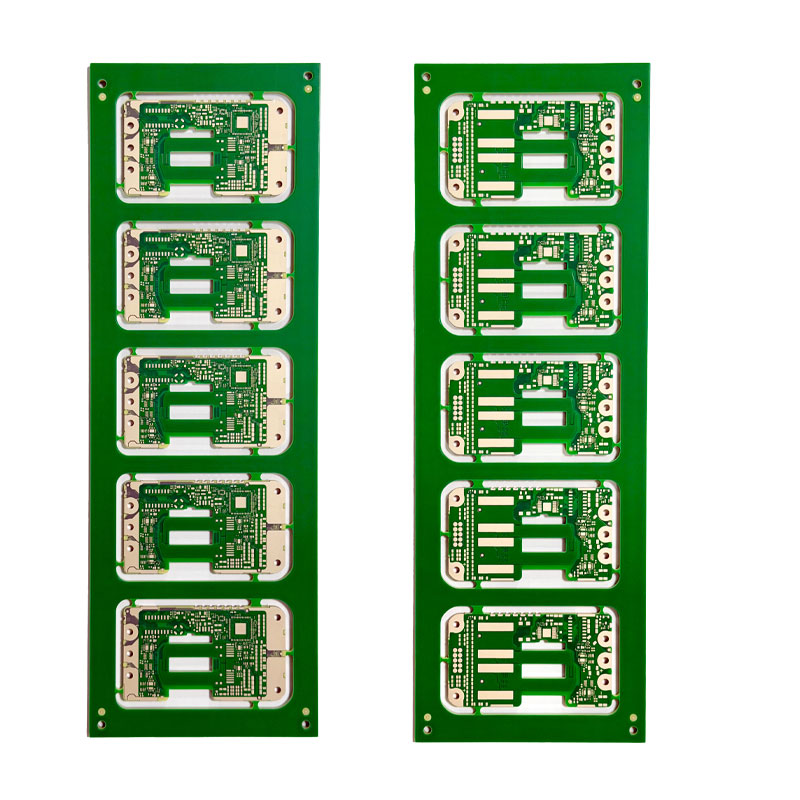
Placement: Order and Grouping
Placement begins with the parts that cannot be moved, which are the connectors and the features that the mechanical drawing fixes. Those are locked before anything else is placed, because a connector that moves later invalidates the enclosure, the cable lengths and the panel design all at once.
The rest follows the signal flow. Core devices are placed next to their supporting components, the fast interfaces are positioned where their routing can be kept short, and the switching supplies are pushed to a part of the board where their noise can be contained. Working in this order is described in the notes on the order in which components are placed, and it is faster than placing by convenience and then repairing the consequences.
Routing: Order, Widths and Reference
Routing order matters as much as placement order. Critical nets are routed first, while the board is empty and the shortest path is available: clocks, differential pairs, memory buses and anything with a length or impedance requirement. General signals come afterwards, and power is planned rather than poured at the end.
Widths are chosen from the rules rather than from convenience, and every net is routed over a plane that gives its return current a defined path. Changing the layer of a net changes its impedance and its return path, so a routing that is checked for continuity of the reference is more reliable than one that is only checked for continuity of the signal. The scope of the rule set is described in the design rules that shorten a layout.
Verification: DRC and Its Limits
The design rule check compares the finished layout against the rules that were set, and reports the violations. It catches copper that is too close, holes that are too near each other, traces that are narrower than the process can hold, and solder mask that does not cover what it should.
What it cannot do is decide whether the design is correct. A rule set that permits a one millimetre clearance will not report a one millimetre clearance that should have been five, and a plane that is continuous in copper but wrong in intent is invisible to the tool. The rules that keep a board manufacturable are a starting set, not a substitute for review, and the design still has to be read by a person.
Outputs and Documentation
The output package is part of the design, not an afterthought. Gerber or equivalent layer data, the drill table, the stack-up drawing, the fabrication notes and the assembly data all have to agree with each other, and the numbering of the layers has to be unambiguous.
Documentation is what makes the design reviewable by the fabricator and repeatable by the assembler. A drawing that states the finished thickness, the copper weight, the impedance targets and the surface finish removes the assumptions that would otherwise be made on the design’s behalf.

FAQ
Should the rules be set before or after the placement? Before. Rules that are added afterwards are checked afterwards, which means the layout has to be re-examined rather than drawn correctly in the first place.
How complete should the schematic be before layout starts? Complete enough to compile without errors that matter. Moving to layout with unresolved single-pin nets guarantees a second pass over the same ground.
Is a clean DRC enough to release a design? No. It shows that the design obeys its own rules, which is necessary and not sufficient. A person still has to confirm that the rules were the right ones.



1 Comment
Migrating Design Data Between EDA Platforms - Kingda
[…] leaves a design that looks correct and connects the wrong pins. Checking these is part of the workflow that runs from rules to DRC and it belongs before the layout […]