
High Speed PCB Layout: Floorplanning and Routing Order
High speed design is often discussed as a list of routing rules, but most of the difficulty appears earlier, when the floorplan and the routing order are decided. Two boards with the same stackup and the same components can differ by a factor of two in how well their fast interfaces behave, simply because one of them was planned before the first trace was drawn. Layout principles matter most in the first day of work, not in the last.
Start With the Interfaces, Not the Components
Most designers place the connectors and the large components first and then discover that the fast interfaces are trapped. A better sequence starts by identifying the critical interfaces and drawing their intended paths on paper before any placement is fixed. That sketch shows where the routing channels must run and which parts have to sit close together for timing reasons.
Only after the critical paths are defined should the rest of the placement be filled in. This approach costs an hour at the beginning and saves days later, because moving a single memory device after routing has begun invalidates far more work than moving it during planning. It also makes the layer assignment decision much easier, since the number of crossing directions is now known.
Layer Assignment and Reference Planes
A high speed stackup should place every signal layer next to a solid plane, ideally with the plane closer than the other signal layer to keep the return path tight. Putting fast routing on both sides of the same ground plane is perfectly acceptable; putting it between two power planes is not. The reference for each signal layer should be decided before routing begins and recorded in the stackup drawing.

Signals that change layers need their reference to change with them. Where two signal layers share the same reference, a via transition is harmless. Where they do not, the return current has to find a path between the two planes, and a stitch capacitor or a ground via next to the signal via provides it. Our notes on impedance tolerance in controlled impedance boards explain how the stackup geometry converts into a target impedance.
Routing Order and Channel Planning
Route the fastest and most constrained nets first, while you still have the whole board available. Memory buses, clock distribution and high speed serial pairs should claim their channels before the power distribution and the slow control signals fill the remaining space. A useful habit is to reserve the layer directly beneath a bus for its reference and nothing else.
Channel planning means deciding where bundles of signals will run as groups rather than letting them spread across the board. Grouped routing keeps reference continuity easy to check, makes length matching practical and prevents the accidental situation where a fast pair has to cross a plane split to reach its destination. Slow signals should be given the awkward paths, because they tolerate them.
Length Matching and Timing
Length matching is about time, not about geometry for its own sake. The tolerance comes from the interface specification, converted into time and then into distance using the propagation velocity of the laminate. Once the budget is known, most designs can be matched by adding controlled serpentine sections in the same channel rather than by routing each trace differently.
Match within a group, and keep the added length symmetrical so that the differential or single ended pairs do not pick up skew from the matching itself. Serpentine sections should avoid tight coupling between adjacent turns, which otherwise converts the added delay into crosstalk. Width and spacing of matched sections should stay consistent along the whole group.
Crosstalk Control Without Overhead
Crosstalk is controlled by separation, parallel length and the proximity of the return path. In most designs, two of those three are fixed by the stackup and the routing density, so the designer controls separation and length. A simple rule is to increase spacing where a trace runs parallel to a victim for a long distance, and to accept tighter spacing where the parallel run is short.
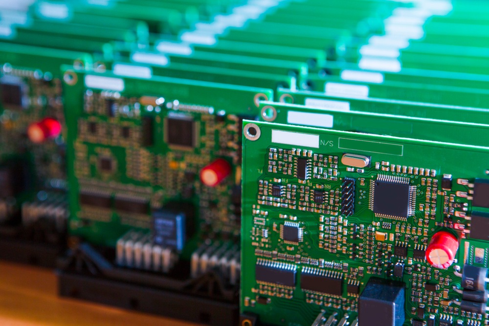
Where a fast net must run beside a sensitive analogue node, insert a grounded trace between them and connect both ends to the reference plane. This fence costs one routing channel and removes most of the coupling. Our guidance on routing high frequency traces and data buses covers the same principle at the level of individual bus groups.
Power Distribution as Part of the Layout
A power distribution network is not only a schematic concern. The path from the regulator to the switching devices sets the impedance the supply presents to fast current demand, and a narrow, long path turns a clean rail into one that sags on every edge. Wide copper, short paths and local decoupling placed at the pins are layout features, not schematic ones.
Placing decoupling is a discipline of its own. The capacitor must be close to the pin, with a short return path to the reference plane, otherwise its inductance cancels the benefit. Grouping several capacitors near a device and connecting them with a wide stub usually works better than scattering them across the board, because the loop area for each capacitor determines how well it performs.
Reviewing the Layout Before Release
Finish with a structured review rather than a visual scan. Check reference continuity for every fast net, confirm impedance targets against the actual stackup, verify that length tolerances are met, and inspect every layer transition for a return via. Recording the result turns a subjective judgement into a checklist that the next design can reuse.
The order of the checks matters less than doing them consistently. Our outline of a PCB layout planning strategy covers how to schedule this work so that placement, routing and review each get the time they need rather than being compressed into the final days before a fabrication deadline.
Mistakes That Show Up Late
The most expensive mistakes in a high speed PCB layout are usually small ones made early. A split reference plane drawn before the fast nets were known, a connector placed so that its pinout forces a crossing, or a decoupling capacitor moved for mechanical reasons and never moved back. None of these is visible in a schematic review, and all of them appear during validation.
A second family of mistakes comes from late changes. Adding a test point to a matched pair, changing a package for a cheaper alternative, or squeezing in one more net after routing is complete all disturb the plan that made the board work. Keeping a record of the critical nets, and checking every change against that record, catches most of them before they reach fabrication.
FAQ
Do I need to simulate a high speed board before manufacturing? Simulation is most valuable for long buses, differential pairs and any interface where the margin is already small. For shorter routes with comfortable timing budgets, a careful layout review guided by the stackup and the interface specification is usually sufficient and much faster.
How much does layer count really matter? It matters mainly because it decides how many signals can have a dedicated reference plane. Four layers with a proper ground plane can outperform six layers arranged badly. Choose the layer count that lets every fast signal see a continuous reference, then use the remaining layers for power and slow routing.
Is it worth matching lengths that the specification does not require? Usually not. Adding serpentine sections consumes routing space, adds crosstalk risk and lengthens the design cycle. Where the interface does not specify a tolerance, estimate the timing margin from the propagation delay and the setup and hold window, and match only to the extent that the margin requires.