Robot PCB Design: Motor Noise, Grounding and Sensors
A robot controller board lives in an electrical environment that is hostile to electronics. Motors draw large currents in pulses, switching converters generate high frequency noise, sensors return signals in the millivolt range, and the whole assembly is often packed into a volume smaller than a shoebox. Designing the board means designing the environment, because no amount of filtering will rescue a layout in which the power and the signal return paths are shared.
What the Board Has to Survive
Beyond the electrical noise, a robot PCB sees vibration from the motion it controls, temperature cycles from the duty cycle of the drive, and in many cases contamination from the process it performs. It is frequently a safety related component, which means the failure of a signal has to lead to a safe state rather than to an unintended motion.
The consequence is that the design has to be robust in three senses at once: immune to the noise it generates, mechanically secure in a vibrating machine and electrically predictable at the moment it matters. Requirements of that kind are met by architecture and layout rather than by selecting better parts.
Power Architecture and Motor Noise
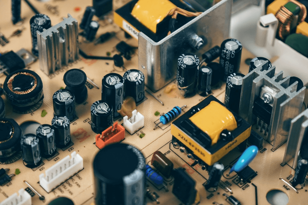
Motor drive is the dominant source of disturbance. A pulse width modulated drive switches a large current in a few tens of nanoseconds, and the resulting current loop radiates a broad spectrum that includes the frequencies used by the control electronics. The first defence is physical: keep the drive stage and its high current loop compact, and put distance between that loop and the control section.
The second defence is in the layout of the supply itself. The converter that feeds the logic should have its own input capacitance close to the switching stage, its own inductor and a clean ground reference, because noise that is superimposed on the logic supply will appear in the analogue measurements and in the timing of the control loop. The rules that govern a switching converter layout are described in DC to DC converter layout and routing.
Grounding Strategy
A robot board usually has at least three ground domains: the high current power ground, the digital ground and the analogue or sensor ground. They must be connected, and the question is where. The usual answer is a single reference point where the currents that flow in each domain cannot share a conductor, with the high current return kept away from the signal return path.
A solid plane is preferred where the design allows it, because it gives every signal a return path directly beneath it. Where separate planes are used, they should be joined at one point near the power entry so that the high current does not flow through the analogue reference. The reasoning behind these arrangements is set out in mixed signal PCB design guidelines.
Sensor Interfaces and Small Signals
Position encoders, current shunts, thermocouples, strain gauges and photodetectors all produce signals that are small compared with the noise around them. Two techniques do most of the work: amplify the signal close to its source so that the long connection carries a larger voltage, and use a differential or a current loop connection so that the noise picked up by the cable is common to both conductors.
The layout around the amplifier matters as much as the circuit. Keep the input traces short and guarded, keep the feedback network close to the device, and keep the reference for the analogue conversion connected to the same point as the sensor return. A ground difference of a few millivolts between the sensor and the converter appears directly as an error in the measurement.
Communication Buses
Field buses such as CAN and industrial Ethernet are designed to tolerate noise, but they only do so when the physical layer is correct. A differential pair with the specified impedance, terminated at both ends where the standard requires it, and routed over a continuous reference plane will survive an electrical environment that destroys a poorly laid out link. The routing rules that apply to those pairs, including length matching and reference continuity, are the same ones described in high frequency trace and data bus routing.
Isolation is the other half of the answer. Where the controller talks to a drive or to a remote node at a different potential, an isolated transceiver removes the ground loop that would otherwise carry the motor current through the signal reference. The isolation barrier should be placed where the two grounds genuinely meet, and its creepage and clearance have to satisfy the applicable safety standard.
Mechanical and Environmental Design
The board is a structural component. Connectors that carry motor current and encoder cables are levered when a cable is pulled, so their mounting must be reinforced or supported by the chassis rather than by the solder joints alone. Large components should be placed away from areas of maximum deflection, and heavy parts such as transformers should be supported at both ends.
Thermal design follows the duty cycle. A drive stage that operates intermittently can rely on the thermal mass of the copper and of the chassis, while one that runs continuously needs a defined conduction path into the mounting surface. Thermal vias under power devices transfer heat into the internal copper, and the mounting arrangement has to conduct that heat into the frame rather than insulating it.
Safety and Functional Isolation
A machine that can injure a person needs more than a well designed board. The safety function is normally implemented so that the loss of any single component leads to a safe state, which means the enable path is a deliberate chain rather than a logic output, and the board provides a monitored input for a guard or an emergency stop. The layout should keep the safety related conductors physically separated from the functional ones so that a fault cannot bridge them.
Where mains or a high voltage bus is present, the isolation and the creepage distances are determined by the applicable standard and by the tracking resistance of the laminate. The clearances are measured along the board surface as well as through the air, and slots or cutouts are often used to increase the surface distance without increasing the size of the board.
Testing the Board in the System
A controller board that works on the bench can still fail in the machine, because the noise environment only exists when the motors are running. The verification should therefore be performed with the drive operating at the worst case load and switching frequency, with the sensors connected through their real cables and with the enclosure closed.
Useful measurements include the noise on the supply rails, the error in the analogue channels with the drive running, the eye or the differential signal quality on the field bus and the temperature of the power stage after a representative duty cycle. A board that passes those tests is a board that has been designed rather than one that has been lucky.
FAQ
Should the motor ground and the logic ground be separate? They should be separated in the sense that they must not share a conductor carrying high current, but they are joined at a defined point so that the design has a single reference.
Can a single board controller and drive be built? It can, and it is common, but the layout discipline is stricter because the noise source and the sensitive circuits share a substrate.
Is isolation always needed? Where the controller and the drive are at different potentials or where a cable leaves the enclosure, isolation removes the ground loop and is normally required by the safety assessment.