
What Makes a Good PCB Design? A Practical View
A good PCB design is easy to recognise and hard to define, because the qualities that make it good are mostly invisible until something goes wrong. A board that works in the laboratory, builds without questions, tests without difficulty and survives a few years in the field has satisfied all of them, and none of those outcomes is an accident. The criteria below are the ones that separate a design that happens to work from one that can be produced and supported.
It Does What It Was Meant to Do
The first requirement is that the design functions across the full range of conditions it will see: temperature, supply variation, ageing and tolerance. That means the schematic has been analysed rather than simulated at one operating point, and the layout supports the analysis by keeping the critical nets short, the references solid and the sensitive circuits away from the noisy ones.
It also means the design has margin. A circuit that works exactly at its specification limit in the laboratory has no room for a component tolerance, a supply sag or a warm day, and it will fail in the field. A good PCB design leaves the margin that the analysis identified rather than consuming it to satisfy a layout preference.
It Can Be Built as Drawn
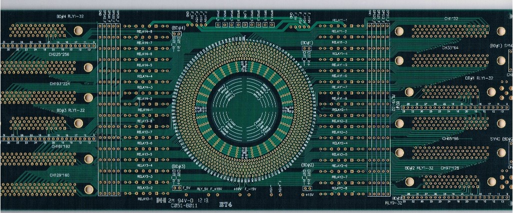
A design that cannot be manufactured as drawn is not finished, however well it performs in simulation. Every dimension on the board should be within the capability of the shop that will build it, from the smallest annular ring to the tightest solder mask bridge, and those limits should be confirmed rather than assumed from a default rule file. When the design is on the edge of the process window, the yield falls and the cost rises.
Manufacturability also covers the assembly. Footprints must match the components, paste apertures must deposit the right volume, and the panelization must allow the boards to be handled and separated without damage. These are the checks that decide whether the first build arrives on schedule. Our notes on PCB manufacturing processes describe what each step requires.
It Can Be Tested and Serviced
A board that cannot be tested cannot be produced reliably, because there is no way to tell a good unit from a marginal one. Test access should be planned at layout time, with points on a usable grid, clear of tall components and reachable by the fixture that will actually be used. Programming and debug access belongs to the same category, since a board that must be disassembled to update its firmware will not be updated.
Serviceability is the other half. Parts that are likely to be replaced should be accessible, connectors should have room to be mated by hand, and the board should be removable without dismantling the whole product. Each of these decisions is cheap at layout time and expensive afterwards.
It Is Documented Well Enough to Repeat
Documentation is what allows a board to be built again in five years, by a different team, without a conversation with the original designer. That means a fabrication drawing with a stackup, a finish specification, an impedance requirement and a tolerance list, and an assembly drawing with polarity, orientation and any special process instruction. A design whose documentation is a verbal explanation is a design that will be rebuilt by guesswork.
The documentation should also record the decisions. Why a particular laminate was chosen, why a net was routed on an inner layer, and why a component was placed away from the rest are all useful to a future engineer, and none of them can be recovered from the artwork. A short design note attached to the release costs an hour and saves a project. Our notes on PCB design quality characteristics list the items worth recording.
It Survives the Environment
The environment the board will actually experience is often harsher than the one it was designed for. Vibration loosens connectors and cracks solder joints, humidity encourages electrochemical migration between fine features, and thermal cycling fatigues plated barrels and large joints. A good design accounts for these with clearance, coating, strain relief, conformal coating and a component derating that leaves margin.
It also accounts for handling. Boards are dropped, flexed, stacked and cleaned during production and assembly, and a design that assumes perfect handling will produce failures that are attributed to the process. Edge clearances, stiffeners and sensible component placement relative to the outline all reduce that risk.
It Is Reviewed by Someone Else
The last criterion is procedural. A design reviewed by its author alone will contain the errors the author did not notice, because attention follows intention rather than reality. A review by someone else, with a checklist and a focus on the areas that carry the most risk, catches most of those errors in a few hours and is the cheapest engineering activity available.
The review should cover the layout, the documentation and the mechanical fit together, and its findings should be recorded with a decision for each. Our notes on PCB layout review mistakes and PCBA development describe how the review fits into the wider project flow.
Design Intent and What Erodes It
Design intent is the set of reasons behind a layout, and most defects are a failure to preserve it. A trace was routed on an inner layer because it needed a controlled impedance; a component was placed away from the power stage because it is temperature sensitive; a pad was given a thermal relief because it must be hand soldered. When a later change moves that trace, component or pad, the reason disappears with it unless someone wrote it down.
Preserving design intent is largely a matter of communication. Note the constraints on the drawing or in a short design note, mark the critical areas on a review copy, and tell the assembly house which pads are relieved and which are solid. A design that carries its reasoning with it survives the changes that every product goes through, while one that does not will gradually accumulate small edits that erode the margin the original analysis provided.
Early Signals of a Design That Will Be Reworked
Some warning signs appear before the board is even released. A layout with no design note, a stackup that was never discussed with a fabricator, a bill of materials with components that are not stocked, and a test plan that does not exist are all indicators that the project is relying on luck. None of them are electrical faults, and each of them predicts a delay.
The other signals are visible in the layout itself. A board where the critical nets are the last to be routed, where the decoupling is arranged for tidiness rather than function, or where the same net changes reference layers several times has been built around the routing rather than around the electrical requirement. Catching these patterns in a review is what turns a design that works on one bench into one that works in production.
FAQ
What separates a good design from a working one? Margin, manufacturability, testability and documentation. A working design satisfies the functional requirement; a good one also builds, tests and supports without repeated engineering effort.
How much documentation is enough? Enough that a different engineer could rebuild the board without asking a question. That normally means a stackup, a finish and tolerance specification, an assembly drawing and a short design note.
Can a design be too complex to review? It can be too large to review in one session, which is why a checklist and a division of areas between reviewers works better than an open meeting. Structured review scales; unstructured does not.