HDI 1+N+1 vs 2+N+2: Microvia Stackup Comparison
The shorthand that describes a high density board, such as 1+N+1 or 2+N+2, encodes how many microvia layers have been added to each side of an ordinary core. The first number is the count of build-up layers on top, N is the conventional core in the middle and the last number is the count on the bottom. The difference between the two structures is one extra build-up layer per side, and that single layer changes the routing density, the cost and the manufacturing difficulty substantially.
What a Microvia Is
A microvia is a small hole, typically 50 to 150 microns in diameter, formed by laser rather than by a mechanical drill and used to connect an outer layer to the layer immediately beneath it. Because it spans only one dielectric layer, the aspect ratio is favourable and the hole can be filled and plated flat, which is what allows a pad to be placed directly over it.
The alternative is a mechanically drilled through hole of 0.15 to 0.3 mm and larger. It consumes routing area on every layer it passes through, and it leaves a stub in a thick board. Replacing through holes with microvias where the connection is short is what makes fine pitch ball array packages routable on a small board at all, and the general via selection problem is described in via and stack selection.
How Build-Up Layers Are Made
High density boards are produced by sequential lamination, often abbreviated SBU for sequential build-up. The core is fabricated conventionally, then a dielectric layer is laminated onto it, laser drilled, desmeared, plated and patterned. Each additional build-up layer repeats that cycle, which is why the layer count in the shorthand is also a count of the lamination and drilling cycles the panel must survive.
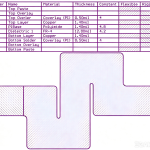
Microvias are then arranged in one of two ways. A stacked microvia sits directly on top of the one below, layer one to layer two to layer three, which gives the highest density and the shortest path but concentrates mechanical and thermal stress in a vertical column. A staggered arrangement offsets each via horizontally, which is easier to fill reliably and distributes the stress, at the cost of some routing area. The plating and filling behaviour that dictates which is possible is covered in via filling in HDI.

1+N+1: One Build-Up Layer per Side
This is the workhorse of the category. One build-up layer on each side means one laser drilling operation and one lamination cycle beyond the core, so the process complexity and the cost are both moderate and the yield is high. A six layer 1+N+1 board, for example, is a four layer core with one microvia layer added to each face.
Its routing capability suits ball array packages at 0.5 mm pitch and conventional high density consumer and IoT assemblies. It does not offer enough escape layers for the smallest packages, where the ball pitch falls to 0.4 mm or below and each row of balls needs an escape route on its own layer. Prototype pricing for this structure typically falls in the middle hundreds of dollars, and production pricing in the tens of dollars per board.
2+N+2: Two Build-Up Layers per Side
Adding a second build-up layer on each side doubles the number of sequential lamination and laser drilling cycles, and it is those extra cycles that the price reflects. In exchange the design gains two more routing layers in the same board thickness, which is what makes 0.4 mm and finer ball pitch packages routable without increasing the board.
The second benefit is electrical. Shorter escape paths and more reference-plane layers improve signal integrity, which matters to high speed processors, 5G modules and accelerator hardware. The cost is real: more lamination, more laser drilling, more via filling and stricter inspection, which pushes both the prototype and the production price roughly to double the 1+N+1 figure.
Comparing the Two
Routing density is the first difference and the most quantifiable. A 1+N+1 stack can normally escape a 0.5 mm pitch array in a conventional way; a 2+N+2 stack reaches 0.4 mm and below. If the largest device on the board has a ball pitch the simpler structure can escape, the extra build-up layer buys nothing.
Reliability behaves differently from density. The 1+N+1 structure has fewer microvias, fewer lamination interfaces and a shorter process, all of which favour yield and long term reliability. The 2+N+2 structure has more opportunities for a via defect, and because the build-up layers are thinner the stacked via columns carry more stress per unit area, so the via arrangement and the fill quality become critical.
Cost and lead time follow the process. One build-up layer per side is roughly half the price of two, with prototypes measured in one to two weeks and production in three to five weeks, while the more complex structure adds a week or more in each case. Where the schedule is tight, that difference is often as decisive as the price.
Manufacturing Consequences
Each additional build-up layer adds a lamination cycle and a laser drilling operation, and each of those is a yield event. The dielectric is thin and the microvia diameter is small, so registration between the via and the pad below it has to be held to a tight tolerance, and the copper filling has to be complete and flat or the next layer will not laminate properly.
Inspection grows with the structure as well. Cross sections are taken to confirm via fill and plating thickness, X-ray verifies registration and the finished impedance is checked with coupons, because the dielectric thickness of a build-up layer is a critical parameter for a controlled impedance line that runs on it.
Choosing Between Them
Start from the package. Identify the finest ball pitch on the board and the number of signal rows that need to escape from beneath it. If a single build-up layer per side provides enough escape layers, the simpler structure is the correct engineering choice, and choosing the more complex one adds cost and risk without adding capability.
Then consider the board thickness and the impedance requirement. Where the stack is thin and the design needs several controlled impedance layers with closely spaced reference planes, the extra build-up layers can be the only way to fit them. Where the board is already thick and the routing is comfortable, they are usually not needed.
Finally, check the fabrication capability of the intended supplier. Not every fabricator offers 2+N+2 with stacked microvias, and the ones that do may restrict the via arrangement or the minimum dielectric thickness. Confirming that before the layout is fixed is far cheaper than discovering it afterwards, and the related question of placing vias inside pads is covered in via in pad treatment.
FAQ
Is 2+N+2 always better than 1+N+1? No. It offers more routing layers and better electrical performance, but at roughly double the cost and with more manufacturing risk. Where a single build-up layer per side can escape every device on the board, the simpler structure is the better choice.
What package pitch does each structure support? A 1+N+1 stack handles ball pitches down to about 0.5 mm in typical designs. A 2+N+2 stack extends that to 0.4 mm and below, which is where the smallest processors and memory packages sit.
Should microvias be stacked or staggered? Stacked vias give the shortest path and the highest density but concentrate stress in a column. Staggered vias distribute the stress and are easier to fill reliably, at the cost of some routing area, and the choice depends on how many cycles the product must survive.
How much more does a 2+N+2 board cost? Roughly double the 1+N+1 price for the same size and layer count, reflecting the additional lamination cycles, laser drilling operations, via filling and inspection. Prototype lead times are also longer by a week or more.