Antipads And Inner Layer Copper Voiding
Every via passes through layers it does not connect to, and on each of those layers the copper must be removed around the barrel. That clearance is the antipad, and its size is one of the few layout parameters that affects impedance, manufacturability and current capacity at the same time. Treating it as an automatic value generated by the design tool is a missed opportunity at best and a source of defects at worst.
This article covers what the antipad does electrically and mechanically, how its size is chosen, and where deliberate copper voiding is the right design decision rather than an artefact of the via.
What The Antipad Does
The clearance around a via barrel on a plane layer performs two functions. It provides the electrical isolation the via needs from the plane, and it defines the capacitance between the via barrel and the plane, which is one of the components that makes a via a discontinuity. A small antipad means more capacitance and a lower local impedance; a large antipad means less capacitance and a longer current detour around the hole.
The current detour is the part that is easy to forget. On a plane carrying return current, the copper removed for one via forces the current to flow around the hole, which lengthens the path and raises the local inductance. Forty vias in a row can carve a significant slot in a plane, and the resulting inductance appears in the return path of every signal that crosses the region.

It helps to think of the clearance in terms of what the via sees. Looking down its length, the barrel is surrounded by alternating rings of copper and void, and each copper ring is a small capacitor plate while each void is a gap in the current path. The transition is therefore a cascade of small capacitors separated by short inductive sections, which is why the behaviour depends on the number of layers the via passes through rather than on any single layer.
Sizing The Clearance
The minimum antipad is set by the fabrication tolerance: the drill position tolerance, the registration between layers, and the minimum annular clearance the process can hold without risking a short between the barrel and the plane. Typical values are in the range of eight to twelve thousandths of an inch of radial clearance for a standard multilayer process, with tighter figures available where the fabricator can hold them.
Above that minimum, the size becomes a design choice. Increasing the antipad reduces via capacitance and raises the impedance of the transition, which helps on a high speed net where the via is already too capacitive. Decreasing it improves the plane integrity and the thermal path for a via that carries current. The two effects pull in opposite directions, which is why the value should be set per via class rather than globally.
<img src="https://www.gopcba.com/wp-content/uploads/2026/08/AI_PCB_article_638737499449721762-1.webp" alt="Plane layer with vias and thermal relief spokes” />
Vias That Carry Current
A via that carries power or a return current has a different set of priorities. Its resistance and its thermal path both depend on the barrel and on the connection to the plane, and a large antipad removes the copper that would otherwise help spread heat. For power vias, multiple barrels in parallel and a generous plane connection usually matter more than the antipad dimension.
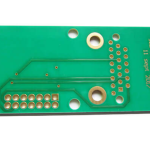
Where a via connects to an internal plane, the connection is normally made by a short spoke pattern, which serves the same purpose as a thermal relief on a pad. The spokes are sized to carry the current without excessive voltage drop, and the number of spokes is chosen so that the plane connection does not become the limiting element in a power path.
Antipads And Impedance Control
On a controlled impedance board the antipad is part of the via model, and its size determines how much the via perturbs the impedance of the trace that passes through it. A via in a fifty ohm line is usually capacitive, so the standard remedy is to remove some of the capacitance by enlarging the antipad on the layers that are not connected, and in some cases by removing the plane clearance entirely on layers that are far from the signal.
The corrections are limited, and a well designed via transition keeps the discontinuity short in electrical terms. Where the via length is a significant fraction of the rise time distance, no antipad adjustment will remove the effect, and the only remaining option is to change the layer assignment so that the signal does not travel through the board. The available via stack options are what determine whether that is possible.
Deliberate Copper Voiding
Copper is sometimes removed from an inner layer for reasons that have nothing to do with vias. A void under a component may be required to keep a metal can from shorting to the plane, to control the capacitance of a specific structure, or to reduce coupling between two regions. Voiding under an antenna, for example, is mandatory rather than optional.
Every deliberate void changes the reference for anything routed over it, so the area should be planned with the routing rather than added afterwards. Crossing a void with a signal trace removes the return path, and the resulting common mode current is one of the more effective ways to fail an emissions test. Where the crossing is unavoidable, a capacitor or a set of stitching vias bridging the void restores the path, and the clearance rules between vias and traces determine how that restoration can be made without introducing a new violation.
Checks And Documentation
Three checks catch most antipad problems. The first is a clearance check against the fabrication rule, run on the final database after any plane edits. The second is an impedance check on the vias of controlled impedance nets, comparing the modelled loss against the budget. The third is a visual review of the plane layers, looking for chains of vias that have effectively cut a plane in two.
Documentation matters because the antipad size is a parameter that will be regenerated by whoever edits the layout next. Stating the clearance in the fabrication drawing, and setting it as a design rule rather than as a manual edit, is what keeps the decision stable through revisions.
That also explains why a via behaves differently depending on where it sits relative to the reference plane that the trace uses. A via whose barrel passes close to its own reference plane presents a larger capacitance than one that passes close to a plane belonging to a different net, and the difference is large enough to matter on a fast link. Reading the stackup with the via in mind, rather than only with the trace in mind, is what makes the transition predictable.
FAQ
Should the antipad be enlarged on all high speed vias? Only where the via is capacitive and the discontinuity is significant. Enlarging it everywhere weakens the plane and adds inductance to the return path, which can be worse than the capacitance the change was meant to remove.
Can a plane be split by vias? Yes, if a row of clearances is wide enough to form a continuous gap. The remedy is to stagger the clearances, to increase the copper between them, or to move some of the vias to another location.
Does the antipad affect the drill to copper distance? It does, and that distance is one of the parameters the fabricator uses to set the minimum annular ring. Reducing the antipad below the process minimum risks a short or an exposed barrel edge, so the value should come from the fabrication capability rather than from the layout tool default.