
Why The Stackup Should Name The Copper Foil
A stackup drawing usually lists the layers, the dielectric thicknesses and the finished board thickness. It rarely says which copper foil is used, and that omission is one of the more common reasons a board measures worse than the model predicted. Foil type, and especially foil roughness, is now a first order parameter at high frequency rather than a purchasing detail.
This article explains why the copper foil belongs in the stackup, what the different types are, and how the omission turns into a performance difference between two boards that were built to the same drawing.
The reason the topic is easy to miss is that foil selection has historically been a fabrication decision, made to suit the shop’s lamination process rather than the electrical requirement.
Foil Types And How They Are Made
Electrodeposited foil is grown on a rotating drum from a copper sulphate solution, and the side that faces the drum is smooth while the side that grows outward is rough. Rolled annealed foil is mechanically reduced from a cast ingot and has a more uniform, generally smoother, grain. Electroplated foil dominates the market because it is cheaper and its roughness can be tailored to give adhesion to the laminate.
The roughness is deliberate. A mechanical key is what holds the foil to the resin, so a smoother foil needs a different adhesion chemistry. That is why the low profile and very low profile foils are supplied with specific bonding treatments, and why substituting one grade for another can change not only the electrical performance but the process window at the laminator.
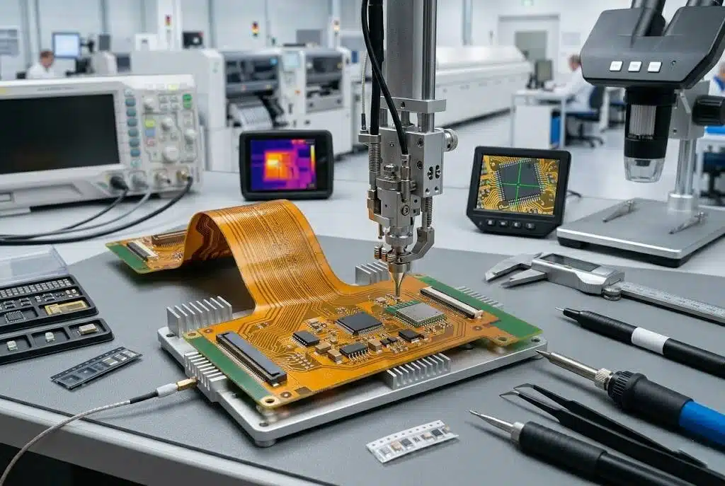
Why Roughness Matters At High Frequency
At high frequency, current is pushed toward the surface of the conductor by the skin effect. If that surface is rough, the current is forced to follow a longer path than the straight-line length of the trace, and the effective resistance rises. The effect is small at low frequency and grows quickly as the skin depth falls below the amplitude of the surface profile.
The consequence is a contribution to insertion loss that no amount of dielectric improvement can remove, which is why a very low loss laminate paired with standard rough foil can measure worse than a mid grade laminate paired with smooth foil. Reading the loss tangent alone and ignoring the conductor is a common mistake in material selection.
How The Requirement Gets Lost
When the stackup is a coordinate table without material names, the shop has freedom to choose the foil it has in stock. Two production runs can then use different foil grades with the same nominal thickness, and the boards will meet the drawing while differing in loss. The designer sees an inconsistency in measurement and no cause in the documentation.
Naming the foil type in the stackup removes the ambiguity. It should appear alongside the dielectric material and the thickness, because those three together determine the electrical behaviour of the layer. Where a low loss laminate has been chosen for the signal layers, the foil on those layers is part of the same decision.
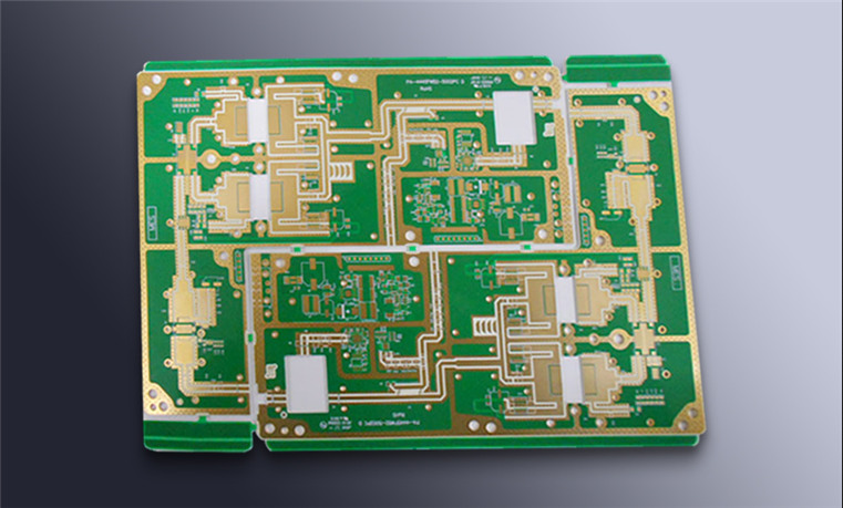
Roughness Figures And Their Limits
Foils are described by roughness parameters measured on the bonding side, and the numbers are quoted for the untreated profile or after the bonding treatment depending on the supplier. The values are not directly comparable between manufacturers, and they are measured over a limited area, so a specification should name a grade and rely on a supplier’s data rather than pick a numeric target.
What matters for a loss budget is the roughness of the surface actually in contact with the laminate on the signal layer, which may be different from the outer layers. Where the loss budget is tight, the modelling should use the foil grade that will be used in production, and that requires knowing the grade at the time the stackup is defined.
Thickness, Tolerance And Process
Foil thickness affects the loss as well, though less than roughness at high frequency. A thicker foil is more expensive and harder to etch into fine features, so the outer layers of a fine pitch design are usually thin while the inner power layers may be thick. Thickness tolerance is also part of the stackup, because a foil that is thicker than nominal moves the dielectric spacing and therefore the impedance.
The tolerance chain matters here: foil thickness, prepreg and core thickness, and plating thickness all interact, and the finished impedance depends on their sum. Specifying any one of them without the others leaves the fabricator to absorb the difference, which usually means the design absorbs it instead. The manufacturing tolerances quoted for the finished layer thickness are the practical expression of that chain.
Where The Foil Interacts With The Stackup
Because the foil is part of the layer, the recording of it belongs in the same document as the layer order. A stackup that names the foil grade on each layer is unambiguous about which layers carry the high speed nets and which are general purpose, and it makes it possible to compare two designs on electrical terms rather than on nominal geometry.
This also gives the fabricator a way to propose substitutions intelligently. A shop that knows the loss requirement can offer an alternative foil with equivalent roughness instead of an alternative with the same thickness and a rougher surface. The layer stack arrangement and the foil choice are decided together, because a design that places high speed signals on the outer layers has less freedom in the foil thickness than one that buries them between planes.
Substitutions And Change Control
When a substitution is unavoidable, the question to ask is whether the electrical behaviour changes. Substituting a foil of the same grade from another supplier is normally transparent. Substituting a different grade with the same thickness is not, and it should be treated as a change requiring the loss budget to be rechecked.
Writing that rule into the fabrication notes costs one sentence. A note that says any substitution of foil grade requires approval, with the reason stated, prevents the situation where a cost reduction in procurement quietly degrades a link that was validated on the first build.
Additional Considerations for This Build
Practical attention to surface roughness pays for itself here, because it decides whether the finished board behaves as the drawing intended. Where the requirement is not stated on the fabrication drawing or in the assembly notes, the shop has to assume a default, and that default is rarely the value the design was simulated with. Stating surface roughness explicitly, together with the tolerance that applies, removes the assumption and keeps the result predictable from batch to batch.
Process Control and Verification
Reviewing the design before the data is released is far cheaper than correcting it after the panel is in the tank, because every step downstream inherits the decision made at the front end. Where a value sits close to a process limit, the drawing should say so, since the shop can then open the process window rather than working to a nominal figure that carries no tolerance.
FAQ
Does foil roughness matter below a few gigahertz? Its contribution grows with frequency, so on a link running at a few hundred megahertz the effect is small compared with dielectric loss. On a multi-gigabit channel it can be a significant share of the total.
Is smoother foil always better? Electrically yes, in terms of loss. The trade is adhesion, which is why very smooth foils come with specific bonding treatments and may narrow the lamination process window. The choice should be made with the fabricator rather than in isolation.
Can the effect be compensated in the driver? Equalisation can compensate for a predictable loss profile, but only within the range the receiver supports. If the extra loss consumes the margin the specification allowed, the link will be marginal regardless of the equaliser.