Solder Mask Bridge Spacing on Fine Pitch Pads
On a fine pitch footprint the solder mask is asked to do something difficult: sit as a narrow wall between two pads that may be less than a tenth of a millimetre apart, survive imaging and development, and remain in place through printing, placement and reflow. When the wall is too narrow for the process, it disappears, and the two pads share a pool of solder that produces a bridge rather than a joint.
What a Solder Mask Bridge Is For
A solder mask bridge is the strip of mask that separates adjacent pads. It prevents solder from wicking between them during reflow, it limits the spread of the paste that is printed on each pad, and it protects the laminate between the conductors. On a coarse footprint none of this requires thought, because the gap between pads is far wider than the process limit.
As pitch shrinks, the bridge width falls while the process limit does not. At some point the requested dam is narrower than the mask can resolve, and the fabricator has to choose between delivering a dam that will not survive or abandoning it and letting the mask open over the gap. Both options are manufacturable; only one of them is what the designer intended.
Minimum Dam Width and Process Capability
The minimum dam width a fabricator can hold depends on the mask material, the imaging method, the copper height beneath and the thickness of the deposit. A thin deposit over thin copper can resolve a narrower dam than a thick deposit over plated traces. The number quoted in a design guide is therefore a capability statement for a particular process rather than a universal limit.
Where the requested width is below the capability, the usual outcome is that the dam is removed during development or peels during reflow. Buying a narrower dam by reducing mask thickness has a cost as well, because a thin mask provides less protection against solder bridging over copper steps.

Registration: The Real Constraint
Even a correctly sized dam can fail if it is not centred. Mask registration is the alignment between the mask artwork and the copper beneath, and it drifts with the same expansion and contraction effects that affect drill registration. A dam that is nominally adequate but shifted toward one pad leaves a wider opening on the other side and a thinner wall on the first.
This is why the useful design number is not the nominal dam width but the minimum width that remains at the edge of the registration window. Designing to that minimum is what prevents a footprint that passes on most panels and fails on the ones produced at the extreme of the tolerance.
Tenting and Via Treatment
Vias in a fine pitch area add a second decision. Tenting covers the via with mask, which is often preferred under a component because it prevents solder from wicking into the barrel, but a tent over a large via will not survive and a tent over a small one can be damaged by the vacuum of the placement machine. Plugging the via and then masking it is the more robust option where the via must be flat.
The choice also interacts with the bridge. Removing mask from a via that sits between two pads removes the dam as well, so a via cannot be placed in the gap if the bridge is required. Moving the via by a fraction of a millimetre is often enough to restore both features, and that decision belongs in the layout rather than in a fabrication note.
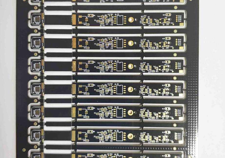
<img src="https://www.gopcba.com/wp-content/uploads/2025/09/高频板.jpg" alt="Mask dam width measurement on a fine pitch footprint” />
When the Bridge Breaks Away
A broken dam leaves mask residue around the pad edge and an opening across the gap. The residue can interfere with paste release, and the opening allows solder to form a continuous bridge between pads during reflow. The defect is usually detected late, because it is a mask defect that only becomes an electrical defect after assembly.
Repeat failures in the same location point at the artwork rather than the process. If the dam is marginal by design, every panel will be at the edge of the window, and the failure rate will follow the process drift rather than any feature of the product.
Designing Pads for a Stable Bridge
The layout levers are pad width and pad length. Reducing pad width increases the pad spacing for a given pitch, which widens the dam, and it also reduces the amount of paste that can be printed. It is usually better to use the minimum pad that still gives a reliable joint than to keep a generous pad and accept an unreliable dam.
Our notes on PCB pad design standards describe how to trade pad geometry against process capability for a given pitch, and where the standard footprint is deliberately overridden to keep the mask bridge inside the process window.
Imaging Methods and Their Limits
Mask imaging methods differ in how faithfully they reproduce a narrow feature. A process with better resolution can hold a narrower dam, but resolution is not the only property that matters; adhesion, edge quality and the ability to cover a step in the copper all affect whether the dam survives the rest of the process.
Our notes on wet film versus dry film photoresist describe the analogous trade-offs in a different process step, and the same reasoning applies here: the choice is made against the geometry being produced rather than against a general preference.
Inspection and Acceptance Criteria
Mask bridges are inspected visually or with automated optical inspection, and the acceptance criterion has to be stated in terms of the required function. A dam that is present but thinner than the nominal value is acceptable if it still prevents bridging; a dam that is absent is a defect regardless of how clean the pads look.
Our notes on SMT inspection methods describe how mask and solder joint inspection are sequenced, and why a mask defect is best caught before assembly rather than interpreted afterwards from a bridge.
Working With the Fabricator
The practical approach is to ask before designing. Sending the intended pitch and pad geometry to the fabricator early will produce a specific dam width that its process can hold, which is a better input than a generic minimum from a design guide. The answer also identifies whether the footprint should be adjusted rather than the mask rule.
At gopcb, fine pitch footprints are reviewed against mask capability before artwork release, so the requested dam is one the process can deliver rather than a number carried over from a previous project on a coarser pitch.
FAQ
Can we simply remove the solder mask between fine pitch pads? Sometimes, and it is a legitimate choice. A mask-defined opening lets the paste deposit define the joint, but it removes the barrier that prevents bridging, so the stencil design has to compensate.
Why is the dam narrower than the artwork? Because of development and registration. The printed feature is reproduced with some loss of width, and any misalignment takes more width from one side than the other.
Does mask colour affect bridge capability? The chemistry and thickness matter more than the colour, though different formulations resolve differently. The relevant question for the fabricator is the minimum width for the specific material and imaging line.