Multilayer PCB Design: Rules That Hold Up in Production
A multilayer PCB is not simply a double-sided board with extra layers. The added layers are a resource that has to be allocated deliberately, and the decisions made in the first hour of layout, about size, layer count and placement, are the ones that are expensive to change later. The rules below are the ones that consistently survive contact with production.
Outline, Size and Layer Count First
The outline is set by the enclosure and the assembly, not by the layout. Within that constraint, a rectangular board with a moderate aspect ratio is easier to panelise, easier to handle and cheaper to assemble than an irregular shape, so the outline should be simplified wherever the product allows it.
Layer count follows from the circuit rather than from preference. It depends on the supply and ground requirements, the board size and the routing density. Four and six layers cover most designs, with four layers giving two routing layers, one ground and one power plane.
Component Placement Sets the Result
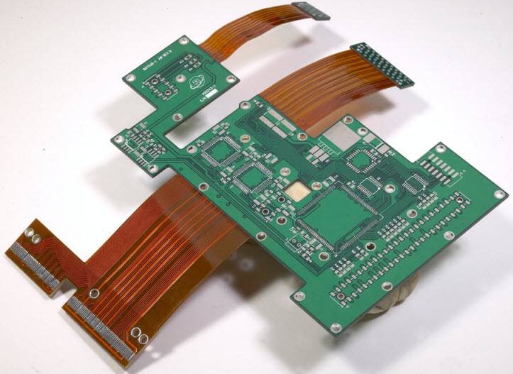
Placement is where the design is won. Critical parts are positioned first: large integrated circuits, power devices, connectors and any component with a fixed mechanical position. Everything else is arranged around them rather than the other way round.
Signal flow should follow the schematic. Grouping parts by function keeps the connections short and makes the layout readable, and an even distribution of components avoids the dense corner that always causes trouble during routing. Placement order and fanout planning belong together at this stage.
Allocating the Layers
With four layers, the usual arrangement is signal on the outer faces with ground and power as the inner planes. That gives every signal layer a reference immediately beside it, which is what makes controlled impedance and quiet returns possible at the same time.
Where more layers are available, the split is between high speed and low speed routing rather than between analogue and digital. The layer stackup should stay symmetric so the panel remains flat through lamination and reflow, and the copper distribution should be reasonably even across each layer.
Routing Direction and Discipline
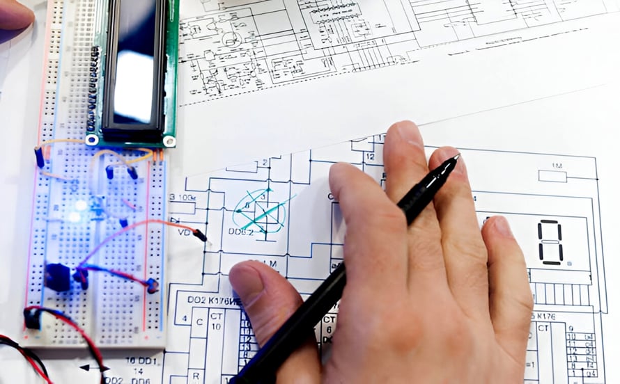
Adjacent signal layers should run in different directions, usually horizontal on one and vertical on the other. This reduces the area over which two layers can couple, and it simplifies fanout from dense devices because each layer serves a different axis.
Other rules follow the same logic. Keep runs short, avoid acute angles and avoid abrupt changes in width, which create reflections and etch anomalies. Where a direction change is necessary, a pair of 45 degree segments is preferable to a single right angle.
Trace Width and Impedance
Width is set by current and by impedance. Power entry traces are sized from the load current using a current calculation, while signal traces are sized to hit their impedance target against the plane below or above them.
For ordinary digital boards without impedance control, a power entry trace might run in the range of 50 to 80 mil while a signal trace runs between 6 and 10 mil. On a controlled impedance design those numbers are replaced by the result of the stackup calculation.
Drill Sizes, Pads and Aspect Ratio
Component hole diameter is derived from the lead, adding a clearance that is typically in the range of 10 to 30 mil, and the pad is then made at least 18 mil larger than the hole. Via pads follow the same principle, with the pad at least 12 mil larger than the via hole.
Aspect ratio is the constraint that ties these together. For dense boards the finished thickness divided by the hole diameter is usually held to about 5 to 1 or better, because a deeper, narrower hole is harder to plate uniformly and its barrel is more likely to crack.
Power and Ground Plane Partitioning
Every voltage distributed on a plane needs its own region, separated from the others by a partition wide enough to be manufacturable, typically somewhere in the range of 20 to 80 mil depending on the voltage. Higher voltages need wider separation.
Connections between a pad and the plane are made with thermal relief spokes to prevent the plane from sinking heat during soldering, and the power plane clearance around a non-connected hole is generous enough to survive the voltage present. Plane integrity across the board matters as much as the partition itself.
Spacing and Interference Control
Minimum spacing is set by the fabricator and by safety requirements. Both outer and inner layers commonly allow a minimum of a few mil, but the spacing should be opened up wherever routing permits, because a generous gap improves yield and reduces the chance of a latent short.
Decoupling is the other half of interference control. A capacitor at the supply pin of every integrated circuit, connected with the shortest possible loop, suppresses the switching current that would otherwise travel across the board and couple into sensitive nets.
Review Before Release
A short checklist catches most problems: confirm that the outline and layer count match the stackup, that every controlled impedance net has been calculated, that the planes are partitioned correctly, and that the drill table reflects the finished hole sizes.
Then check the mechanical details, including the distance from copper to the board edge, the position of tooling and mounting holes and the marking on the correct side. These are the items that most often force a revision after the first mock-up of the assembly.
Material and Thickness Choices
Standard FR-4 with a moderate glass transition temperature suits the majority of multilayer boards. A higher transition temperature is worth specifying where the assembly sees repeated thermal cycling or where lead-free processing pushes the peak temperature close to the material limit.
Finished thickness is chosen for mechanical reasons as much as electrical ones. A thicker board resists bending and holds a heavy connector, while a thin board saves space and improves thermal coupling to a chassis. The stackup has to produce the chosen thickness from standard cores and prepregs.
Board Edge, Tooling and Marking
Copper is held back from the outline so that routing and depanelling do not expose it, and tooling holes are placed where the assembly fixture needs them rather than where space happens to be free. Both should be defined before routing begins, because moving them afterwards disturbs the plane.
Marking follows the same principle. Reference designators should be readable after assembly, which means they cannot sit under the part they identify, and polarity marks belong beside the pad rather than behind it. A legend that cannot be read at the bench is not doing its job.
Where Beginners Lose Time
Most avoidable rework comes from three habits. The first is routing before placement is final, which guarantees that some traces will be ripped up. The second is leaving the plane until last, when the partitions and clearances are already constrained by everything above them.
The third is treating the design rules as an afterthought instead of as the framework for the layout. Rules that are set at the start, and honoured while routing, produce a board that passes inspection with few changes, which is why the checklist matters more than the tool used to run it.
FAQ
How many layers do I need? Four layers handle most designs with a single ground plane and a single power plane. More layers are needed when routing density or additional supply rails cannot be accommodated otherwise.
Should adjacent signal layers run in different directions? Yes. Perpendicular routing between neighbouring layers reduces coupling and makes escape routing from dense packages easier to complete.
What aspect ratio should I target for vias? Around 5 to 1 or better for dense boards. A larger ratio makes uniform plating harder and increases the risk of barrel cracking during thermal cycling.