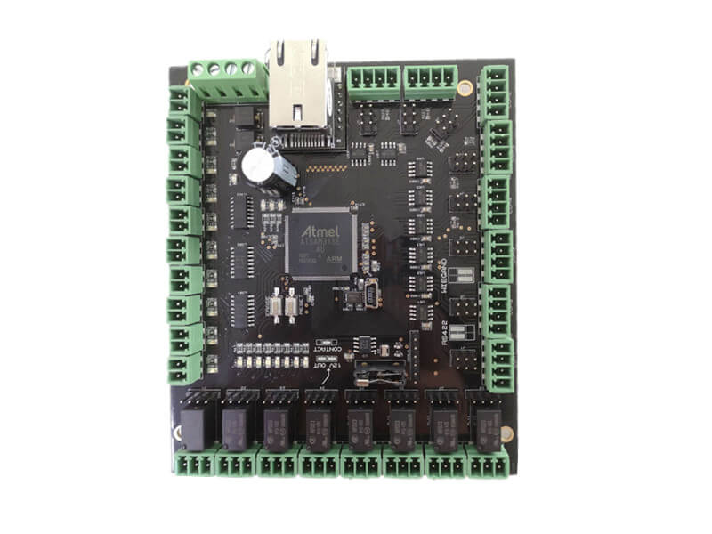
Board To Board Connector: Board to Board Interfaces: Connectors and Return Paths
Where a board has to be connected to another board, the interface between them is where most of the problems appear. The mechanical connection, the impedance of the link and the return path all have to be designed together.
Board to Board Connectors
A board to board connector provides both the electrical connection and the mechanical spacing between the two boards. The stack height is fixed by the connector, and it constrains the components on both boards.
The connector’s pin assignment is a design decision: placing grounds between signal pins reduces crosstalk, and placing the high speed pins adjacent to their returns reduces the loop area. A connector used as a simple feed-through loses that opportunity. Our signal integrity notes describe the arrangement.
The Return Path Across a Connector
Every signal that crosses a connector needs a return that crosses the same connector, close to it. Where the return is provided by the ground plane alone, the current has to find its way to the connector and back, and the path it takes is longer than intended.
The practical rule is to allocate one ground pin for every few signal pins, distributed across the connector rather than concentrated at one end. The rule matters most for the fastest signals.

Differential Pairs Across an Interface
A differential pair that crosses a connector should do so with its two conductors adjacent and with a ground pin nearby. A pair that is split across the connector loses its coupling and radiates.
The pinout should also keep the pair away from single ended signals that switch, because the coupling between them adds noise that the differential receiver rejects only partially.
Flexible Interconnect
A flexible circuit is often used as the link between two boards because it combines the connection with the mechanical compliance. Its impedance depends on the construction, which is different from a rigid board: the conductor is thin and the dielectric is a film.
The impedance should be calculated for the flex construction and matched to the rigid board at both ends. A mismatch at the transition produces a reflection that can be measured. Our flexible processing notes describe the constructions.
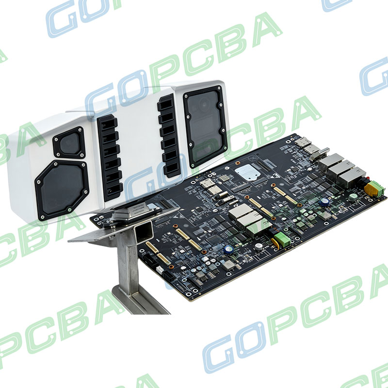
Mechanical Alignment and Tolerance
Two boards connected by a fixed connector must be aligned to within the connector’s tolerance, which is usually tighter than the tolerance on the boards themselves. The alignment is provided by the connector’s own features or by a locating pin.
Where the boards are also fastened to a chassis, the tolerance stack includes the chassis. The design should allow for the accumulation rather than assume that each item is at its nominal dimension.
Cables with High Speed Signals
Where the link is a cable, the impedance of the cable and of the connector have to match the board. The transition between the board and the cable is a discontinuity, and its size determines how much of the signal is reflected.
The transition is improved by keeping the ground return close to the signal at the connector and by avoiding long stub lengths inside the connector footprint.
Testing the Interface
The interface is verified by measuring the impedance across it and by checking the eye diagram under a representative load. The measurement identifies the discontinuity, and the eye diagram shows whether it matters.
Where the link is cabled, the test should include the cable, because the cable is where most of the loss occurs.
Documenting the Interface
The pinout, the stack height, the mating connector and the cable specification all belong on the assembly drawing. A pinout that exists only in a spreadsheet is a pinout that will be wired incorrectly at some point.
Where the two boards are designed by different people, the interface document is the contract between them, and it should be agreed before either layout is complete. Our fabrication notes guidance lists the entries.
Additional Considerations for This Build
Practical attention to flex link pays for itself here, because it decides whether the finished board behaves as the drawing intended. Where the requirement is not stated on the fabrication drawing or in the assembly notes, the shop has to assume a default, and that default is rarely the value the design was simulated with. Stating flex link explicitly, together with the tolerance that applies, removes the assumption and keeps the result predictable from batch to batch.
Process Control and Verification
On a design of this kind, stack height is the item that decides how the rest of the board is arranged. Where a value sits close to a process limit, the drawing should say so, since the shop can then open the process window rather than working to a nominal figure that carries no tolerance. A stack-up that is drawn rather than described removes most of the ambiguity from a quotation, and it lets the fabricator price the board against the dielectric and copper weights that will actually be used.
Where the requirement is not written down, the shop supplies its own default, and the default is chosen for the process rather than for the design. The measurements that matter are the repeatable ones: conductor width and spacing, annular ring, finished hole size, plating thickness and surface finish are all verifiable on a coupon that travels with the panel.
Running a first article through the same checks as the production panel confirms that the two agree, and that comparison is the cheapest form of process control available at prototype stage. Keeping a sample from the panel turns a dispute into a measurement, because the same coupon can be re-examined by both parties without rebuilding the batch.
Process Control and Verification
On a design of this kind, stack height is the item that decides how the rest of the board is arranged. Where a value sits close to a process limit, the drawing should say so, since the shop can then open the process window rather than working to a nominal figure that carries no tolerance. A stack-up that is drawn rather than described removes most of the ambiguity from a quotation, and it lets the fabricator price the board against the dielectric and copper weights that will actually be used.
Where the requirement is not written down, the shop supplies its own default, and the default is chosen for the process rather than for the design.
Process Control and Verification
On a design of this kind, stack height is the item that decides how the rest of the board is arranged. Where a value sits close to a process limit, the drawing should say so, since the shop can then open the process window rather than working to a nominal figure that carries no tolerance. A stack-up that is drawn rather than described removes most of the ambiguity from a quotation, and it lets the fabricator price the board against the dielectric and copper weights that will actually be used.
FAQ
How many ground pins does a connector need? Enough that the return path for the fastest signal is short and that the current density per pin is acceptable. One ground for every four signal pins is a common starting point, distributed rather than grouped.
Should a board to board connector be on the edge? It can be, and edge mounting removes the need for the connector to occupy board area on the top surface. It also constrains the outline and the mechanical tolerance more tightly.
What does gopcb confirm for a board interface? We confirm the connector footprint against the component drawing, the pin one marking, the ground pin allocation and the mechanical stack height. Where the two boards are supplied as a pair we check that the pinouts are mirrored correctly rather than identically.