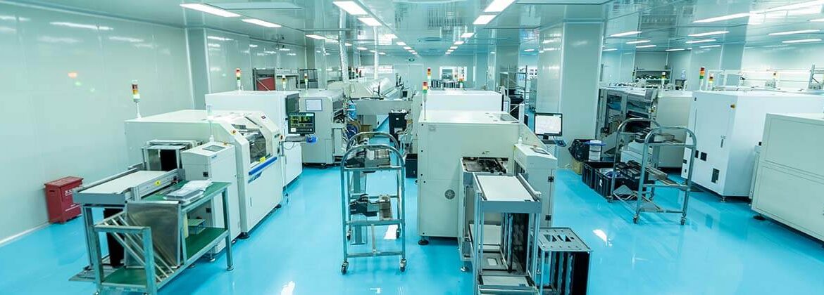
Reflow Soldering Quality: Profile, Defects and Control
Reflow soldering quality is decided long before the board enters the oven. The paste volume, the placement accuracy and the thermal profile together determine whether every joint forms correctly, and no amount of inspection can repair a process that was outside its window when the solder melted.
Why the Profile Matters
The thermal profile is the temperature history that the assembly experiences. It has to bring the paste and the joints above the melting point of the alloy for long enough to form a proper intermetallic layer, while keeping the temperature of the most sensitive component below its limit.
Those two requirements pull against each other on a mixed board where a heavy connector and a thin package sit a few centimetres apart. The profile is a compromise, and measuring it on the actual product rather than on a test vehicle is what makes the compromise meaningful.
The Zones of a Reflow Profile
A typical profile has four parts. Preheating brings the board up gradually, soaking allows the flux to activate and the assembly to equalise in temperature, reflow takes the joints above liquidus, and cooling solidifies the alloy with a controlled microstructure.
Each zone has its own constraints. A ramp that is too fast causes thermal shock and spattering; a soak that is too long consumes the flux; a peak that is too high damages components; and cooling that is too slow produces a coarse grain structure and dull joints.
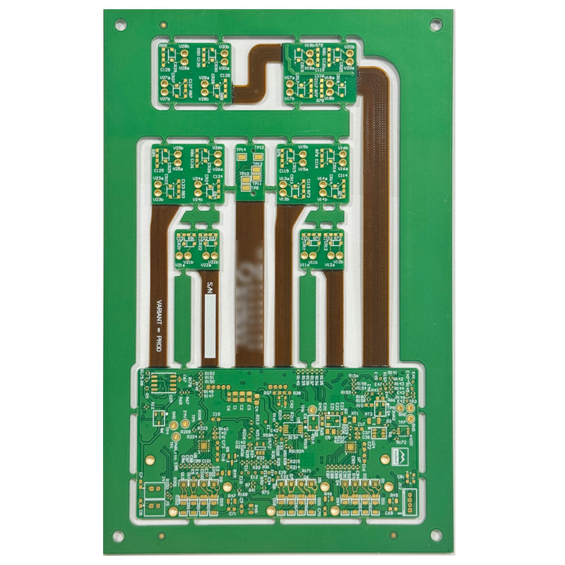
<img src="https://www.gopcba.com/wp-content/uploads/2025/09/多层板.jpg" alt="Solder joint inspection after the reflow soldering process” />
Measuring the Thermal Profile
The thermal profile is verified with thermocouples attached to representative points on the assembly, including the heaviest thermal mass and the most sensitive component. A single measurement on a bare test board says very little about what the production assembly experiences.
Verification is repeated when the product, the oven or the paste changes, and periodically thereafter. It is also worth checking after a conveyor speed adjustment, because the change shifts every zone at once and the effect on the peak is not predictable by eye.
Paste and Stencil Interaction
The paste determines how the alloy behaves and how much flux residue remains. Its particle size, metal content and flux chemistry have to suit the stencil apertures and the profile, and a paste designed for a fast ramp will not perform as intended in a soak profile.
Stencil design controls the volume deposited. Aperture area ratio, stencil thickness and the surface finish of the stencil walls all affect how cleanly the paste releases, and an inconsistent release produces joints that vary across the board.
Defects and Their Causes
Bridging appears where paste volume is excessive or the aperture is poorly shaped. Tombstoning occurs when one end of a chip component heats faster than the other, which is usually a pad geometry or thermal balance problem, and the same class of cause produces component shift on larger parts.
Voids form where flux volatiles cannot escape, and they are worst on large thermal pads and under area array packages. Solder balls come from paste spatter, poor release or moisture, and cold joints indicate that the joint never reached the required temperature.
Atmosphere Control
Nitrogen is used to reduce oxidation during reflow, which improves wetting and widens the process window on fine pitch assemblies. The benefit is greatest with lead-free alloys, whose higher melting point and poorer wetting behaviour leave less margin than the older alloys.
The decision is economic as well as technical. Nitrogen adds running cost, so it is normally reserved for assemblies where the defect rate or the joint quality justifies it, and the solder alloy selection is made at the same time rather than separately.
Inspection and Feedback
Inspection provides the feedback that keeps the process centred. Automated optical inspection catches placement and soldering defects, X-ray reveals hidden joints, and both should feed data back to the printing and placement steps rather than being treated as a final filter.
The useful metric is the type of defect rather than the total. A rising rate of one specific finding points to a specific cause, while an overall number moves for reasons that have nothing to do with quality, such as a change in the inspection program.
Rework Quality
Rework is part of the quality system, not an exception to it. A repaired joint should meet the same criteria as an original one, and the method used to remove and replace the component should be defined so that the result does not depend on which operator performs it.
The heat history matters here. Every reflow pass consumes some of the laminate’s thermal tolerance, so the number of rework cycles should be limited and recorded, and the process should not be used to compensate for a printing problem that could be corrected at source.
Keeping the Process in Control
Control comes from consistency in the inputs: the same paste, the same stencil, the same profile and the same machine settings, with any change recorded and verified. When something does vary, the records make it possible to link the change to the result.
It also comes from monitoring the outputs. Paste volume measurement after printing catches problems before placement, and reviewing the assembly process data at a fixed interval turns quality from a final inspection into a running variable.
Oven Maintenance and Machine Condition
The oven is a machine with consumable parts. Heating elements, blower motors, thermocouples and conveyor components all drift with use, and a zone that runs a few degrees low shifts the profile enough to affect the joints without producing an obvious alarm.
Preventive maintenance should therefore be scheduled against the profile rather than against a calendar alone. Re-verifying the profile after maintenance confirms that the oven was returned to its previous state rather than merely reassembled.
First Article and Process Validation
A first article confirms that the process produces the intended result on the actual product. It includes paste volume measurement, profile verification, visual inspection and X-ray of hidden joints, and it establishes the baseline against which production is compared.
Validation is repeated when the product, the paste, the stencil or the equipment changes. Treating a proven process as transferable between products is one of the more common reasons a mature line produces an unexpected defect rate on a new board.
Working With the Assembly Partner
Questions worth asking are specific. How is the profile established for a new product, how often is it verified, how is paste volume monitored and what happens when a defect trend appears. The answers describe the real control system rather than the certificate.
The design contribution matters as much. Pad geometry, mask clearance, thermal relief and the placement of large parts all influence the process, and a board designed with the assembly method in mind will have a wider window and a lower defect rate than one that was not.
FAQ
What is the most important profile parameter? The time above liquidus, together with the peak temperature. Those two determine whether the joint forms correctly, and the rest of the profile exists to reach them safely.
Does a slower profile always give better joints? No. A profile that is too long degrades the flux and oxidises the surfaces, and it subjects the components to more heat than they need.
Can visual inspection confirm a good joint? A solder joint that looks correct is usually sound, but appearance correlates with quality rather than proving it. Hidden joints such as ball grid arrays require X-ray, and process data is the better indicator overall.