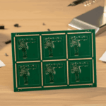
High Current PCB Design: What Works And What Fails
A board that has to carry a hundred amps or more is a different design problem from one that carries a few amps, and the difference is not linear. Doubling the trace width does not double the current a board can carry safely, because the limiting factor is usually temperature rather than voltage drop, and the heat has to leave the board through the dielectric and the surrounding copper.
This article looks at the methods commonly used for high current design, where each of them stops being adequate, and what to do instead.
The distinction that matters is between a board that carries a large current continuously and one that carries it briefly. A short pulse can be far larger than a continuous rating, because the copper does not have time to heat up, and the design rules for the two cases are different.
The Starting Rules Of Thumb
The usual starting point is one amp per millimetre of trace width, which corresponds to roughly forty thousandths of an inch on one ounce copper. It is a useful figure for a moderate temperature rise on an outer layer with reasonable airflow, and it should be treated as a starting point rather than a specification, because it assumes a length short enough that the voltage drop is not the issue.
The second rule is heavier copper. Doubling the thickness halves the resistance for the same trace width, so two ounces of copper behaves like a trace twice as wide. That is often the cheaper answer where there is room in the stackup, and it is the reason the chapter on sizing a trace for current is worth working through rather than relying on a table.

Where The Simple Approach Breaks Down
The first assumption that fails is that the current is distributed evenly. It is not. Current concentrates where the resistance is lowest, so a wide trace does not share the load equally across its width, and the edges carry less than the middle in some geometries and more in others. The consequence is local heating: the trace reaches its temperature limit in a narrow region while the rest of the copper is still cool.
The second assumption that fails is that the joints and vias are not part of the problem. A trace sized for a hundred amps does little good if the current passes through a connector rated for twenty, or through a single via with a small barrel. Those components have their own ratings, and they are usually the limiting item. The third assumption is that the copper is uniform, which it is not after etching, plating and the addition of a surface finish on the exposed areas.
Heat And The Glass Transition Temperature
The real constraint on a high current board is thermal. The laminate has a glass transition temperature, typically between one hundred and forty and one hundred and seventy degrees for ordinary FR-4, and above it the material softens and its electrical properties degrade. That does not mean the board burns, but it does mean the dielectric constant changes, the mechanical stiffness is lost and the reliability of the whole assembly falls.
So the design question is not only how much current a trace can carry but how hot it will become and where that heat can go. A trace on an inner layer is surrounded by dielectric, which is a poor conductor of heat, so it runs hotter than an outer layer trace of the same dimensions. A plane on the other side of the dielectric acts as a heat sink, and the number and arrangement of vias determines how effectively the heat travels into it.
<img src="https://www.gopcba.com/wp-content/uploads/2026/08/High-Speed-PCBs.jpg" alt="Copper busbar bolted to a power board” />
Adding Solder To A Trace
One common practice is to open the solder mask along a heavy trace and fill it with solder during assembly, on the theory that the extra metal reduces resistance. The reasoning is partly right and the method is risky. Solder has a resistivity roughly ten times that of copper, so most of the current continues to flow in the copper underneath even after the trace is filled, and the improvement is far smaller than the increase in cross section suggests.
The risk is greater than the benefit. Solder melts at a low temperature, and a joint that has been relied on as a conductor becomes a break in the circuit when it melts during a fault, which is exactly when the current is highest. The filler can also crack under thermal cycling because its coefficient of expansion differs from the copper, and the process is difficult to control consistently. Where extra conductance is genuinely needed, a copper busbar or a heavier copper layer is the sounder answer.
What Actually Works
Three approaches are dependable. The first is a copper busbar or heavy copper insert, which moves the high current path into a solid conductor that can be sized properly and connected with a bolted or soldered joint. The second is to distribute the current across several layers in parallel, using heavy copper on each, since parallel paths divide both the current and the heat. The third is a metal core or ceramic substrate, where the aluminium or ceramic base spreads heat far better than a laminate and the dielectric is thin enough that the thermal path is short.
Even a metal core board needs its temperature rise checked at high current, because the copper on a thin dielectric can still get hot locally. The manufacturability of the resulting structure also has to be considered, since heavy copper and thick dielectric change the minimum trace width that can be etched and the via aspect ratio that can be plated.
Simulation And Verification
Because current distribution and heat flow are both non uniform, a thermal simulation is the practical way to check a design before it is built. It does not need to be elaborate: a model that includes the copper geometry, the layer stack, the dielectric properties and the assumed current is enough to show where the hot spots will be. Measuring the finished board under load then confirms whether the model was right.
The measurement is worth doing on the first article, with the current applied at the rated value and the temperature recorded at several points, including the vias and the connector terminals rather than only along the trace. Where the result is warmer than expected, the fix is usually more copper or a shorter thermal path rather than more solder. gopcb builds heavy copper and metal core boards and can advise on stackups that carry high current without exceeding the temperature limits of the laminate.
FAQ
Can a normal board carry a hundred and fifty amps? It can, but not as a routine continuous condition. Above the point where the temperature rise becomes the limit, a busbar, parallel layers or a metal substrate is the appropriate answer.
Is filling a trace with solder a good idea? It gives a small improvement in resistance and a large increase in risk, because solder melts during a fault. Heavier copper is the better solution.
Why does an inner layer run hotter than an outer one? Because the surrounding dielectric conducts heat poorly. An inner layer has no direct path to the air and depends on vias and planes to carry heat away.