Assembly Data Preparation: BOM, Placement File and Rotation Errors
The assembly machine is programmed from data, and the data arrives from several sources that must agree. When they do not, the result is a board that is built exactly as instructed and is nevertheless wrong.
What the Data Set Contains
A placement program needs, for each part, a part number that the machine can find in its feeder positions, a position on the board, a rotation and a package definition that matches the actual part.
The bill of materials supplies the part numbers, the computer aided design system supplies the positions, and the library supplies the package. The rotations are the part that no single source owns.
The rotation of a component in the placement file is defined by the library convention, while the rotation of the part in the feeder is defined by the tape. The two conventions differ between tools and between manufacturers, and the difference is the commonest source of a wrongly rotated part.
The Rotation Problem in Detail
A part that is rotationally symmetric cannot be placed wrongly, which is why the problem appears only on polarised parts. A diode, an electrolytic capacitor, a connector and an integrated circuit all have a correct orientation.
Rotation errors are systematic rather than random. If the library defines pin one at the top left and the machine expects it at the bottom right, every part of that type will be rotated by the same amount, and the error will be visible on the first board if anyone looks.
A rotation error of one hundred and eighty degrees on a connector is the kind of mistake that survives a visual inspection and fails at the system test, because the connector still fits its mating part.

Incoming Data Checks
The program should be checked against the bill of materials and against the board before the first build. The checks that catch the most errors are a comparison of the part count, a comparison of the reference designators, and a comparison of the outline positions against the board coordinate system.
The coordinate system matters because a board origin that is defined differently in the design tool and in the machine program produces a uniform offset of every part. A uniform offset is easy to spot on the first board and catastrophic if missed.
Where the design includes a component on both sides, the bottom side coordinates must be mirrored correctly, and this is the second most common source of systematic error.
Rotation Verification on the First Article
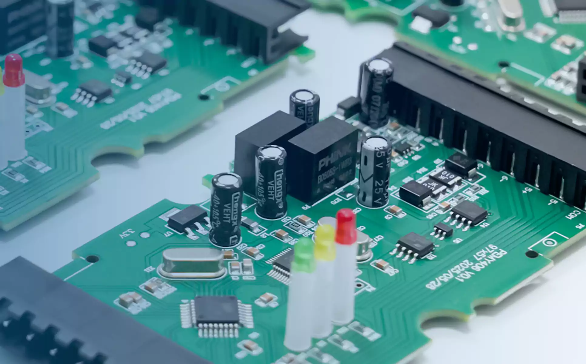
The first article inspection should include the orientation of every polarised part, checked against the assembly drawing rather than against the previous build. Our design release checklist notes where the orientation information should be recorded.
The check is mechanical and quick, and it is the cheapest possible place to find the error. Finding it after reflow means rework, and finding it after assembly means a recall.
Where the same part appears many times, checking one instance is enough only if the rotation error is systematic. Where it is not, the check must cover the parts individually.
Package and Feeder Data
The package definition in the machine library must match the part that will actually be loaded. A library entry for a similar package with a different body size will place the part at the right coordinate with the wrong offset from the nozzle centre.
The feeder data includes the tape pitch, the pocket size and the pickup position. A wrong pitch produces a growing position error as the tape advances, which appears as a placement that drifts along the reel rather than as a single bad part.
The feeder position on the machine must match the program, and the check is a comparison between the setup sheet and the physical machine. Our component selection notes describe the package parameters that the library needs.
Version Control and Change Handling
The program, the bill of materials and the drawing all carry revisions, and they must be revised together. An engineering change that affects the bill of materials but not the program produces a board with a part in the wrong place.
The program should carry the revision of the data it was built from, and the setup sheet should carry the program revision. A setup that is checked against the wrong document is not a check.
The change control process should require that the program is updated and re-verified whenever the placement data changes, and that the first article after a change is inspected as if it were a new build. Our fabrication notes describe how the change is recorded.
The Assembly Drawing’s Role
The assembly drawing shows the location and orientation of every part. It is the document against which the first article is verified, and it is the only document that a human can read quickly.
A drawing that omits a part, or that shows a part without its orientation mark, cannot serve that purpose. The drawing is a deliverable, not a by product of the design.
Where a part is not polarised but is supplied in a directional tape, the drawing should note it, because the tape orientation is what the machine uses. Our inspection notes describe how the automated system verifies what the drawing specifies.
Verification After Build
Automated optical inspection can verify the presence and orientation of parts where the program has a reference image. It cannot verify a part that is correctly placed but electrically wrong.
Electrical test verifies connectivity, which catches a rotated part only where the rotation changes the net connections. A part rotated by one hundred and eighty degrees in a symmetric footprint may connect the same nets and be electrically correct and functionally wrong.
That case is why the functional test and the first article visual check both matter, and why the design should avoid symmetric footprints for polarised parts wherever the package allows. Our solder defects notes describe the assembly faults that electrical test does not catch.
Process Control and Verification
On a design of this kind, rotation is the item that decides how the rest of the board is arranged. The process window is set by the narrowest step in the flow, so an improvement anywhere else shows up as margin rather than as yield until that step is addressed. A short note on the drawing about handling, storage or packaging is often worth more than an extra decimal place on a tolerance.
Process Control and Verification
On a design of this kind, rotation is the item that decides how the rest of the board is arranged. The process window is set by the narrowest step in the flow, so an improvement anywhere else shows up as margin rather than as yield until that step is addressed. A short note on the drawing about handling, storage or packaging is often worth more than an extra decimal place on a tolerance.
FAQ
Who owns the rotation data? Nobody owns it exclusively, which is the problem. It should be verified by the assembly house against the assembly drawing and recorded as a checked item.
Can the design eliminate rotation errors? It can reduce them by using asymmetric footprints and clear orientation marks, but the program still has to carry the rotation correctly.
What does gopcb provide for assembly data? We provide a data check against the bill of materials and the drawing before programming, first article inspection of every polarised part, records of the program and data revisions used, and a change control process that requires re-verification after any data change.