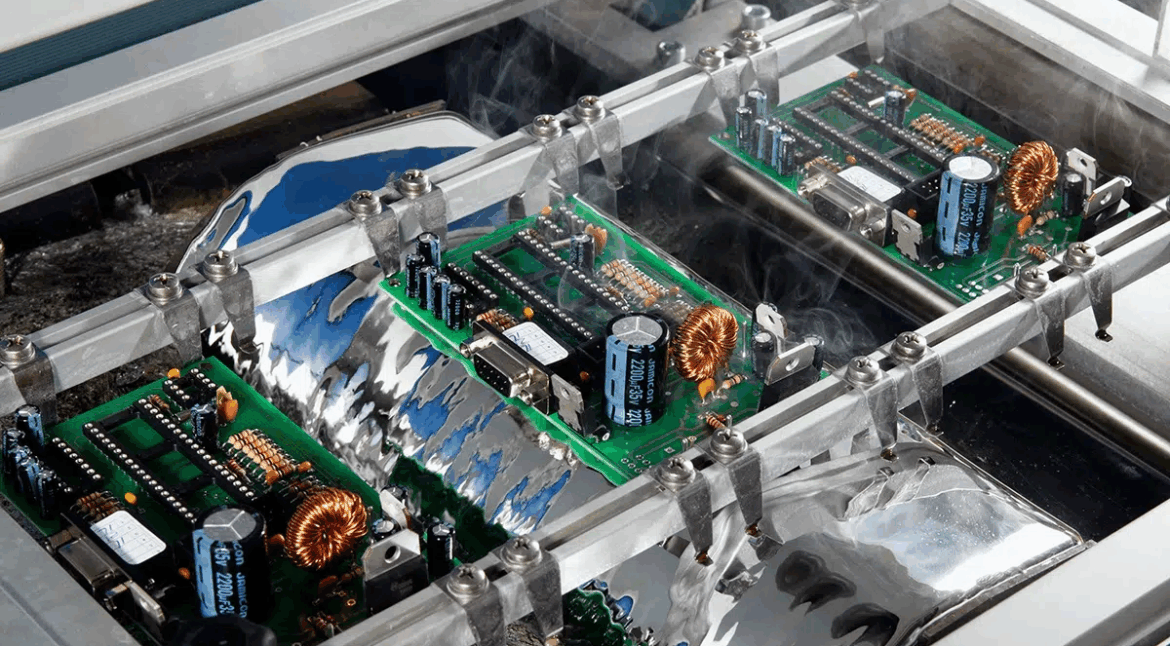
Assembling MEMS Flow Sensors on a Production Line
A micro electro mechanical flow sensor measures the movement of air or gas across a small heated element or a diaphragm. The sensing structure is on the scale of tens of micrometres, and it is packaged in a cavity that has to be open to the medium being measured while remaining sealed against dust, moisture and the flux and cleaning chemistry of the assembly process.
That combination is what makes the assembly step the hardest part of the product. The sensor has to be handled like a component, placed like a component and reflowed like a component, while the opening that lets the air in must not be blocked by paste, by flux or by the conformal coating that protects the rest of the board.
How the Sensor Is Built
The sensing element is usually a thin membrane with a heater and one or more temperature sensing elements, fabricated on a silicon wafer and then released by etching from the back. The released membrane is fragile, which sets the handling requirement. A protective cap, sometimes with an acoustic or fluidic port, is bonded over the die at wafer level or at package level, and that cap is what makes the part placeable.
The package itself is typically a land grid array or a small leadless package with a port on the top or on the side. The port is a defined opening with a specified internal volume, and the response of the sensor depends on that volume as well as on the membrane. Anything that changes the volume, such as a partial blockage or a residue, shifts the calibration and the response time.
<img src="https://www.gopcba.com/wp-content/uploads/2026/08/RoHS-Circuit-Boards-1536×640.jpg.webp" alt="MEMS flow sensor placed on a PCB with an open port” />
Placement and Handling
The sensor is normally supplied on tape and reel with a protective film over the port, and that film should stay in place until after the assembly process is complete. Removing it early exposes the port to paste, to flux and to the vacuum nozzle of the placement machine. The pick and place process should use a nozzle that contacts the cap rather than the port area, and the placement force has to be within the range the package can tolerate.
Orientation matters as much as position. A port that is intended to face away from the board must not be rotated towards it, and a sensor with a defined flow direction has to be placed so that the direction matches the channel in the housing. Because the part is small and symmetric, an orientation error is easy to make and hard to see, so the footprint should carry an unambiguous polarity or orientation marking and the assembly drawing should show it explicitly.
Reflow Requirements
Most flow sensors are rated for a lead free reflow profile, but the rating depends on the internal construction. A part with a polymer cap or an adhesive bond has a lower temperature limit than one with a silicon or metal cap bonded by a high temperature process. The profile has to be checked against the limit, and the time above liquidus matters as much as the peak, because the adhesive continues to cure or to degrade throughout that period.
Moisture is the other reflow risk. A package with a cavity can absorb moisture that flashes to steam at reflow temperature, and the resulting pressure can delaminate the cap or crack the seal. This is why the parts carry a moisture sensitivity level and why the storage and baking rules have to be followed. A part that has been exposed beyond the floor life should be baked according to the supplier instruction rather than reflowed as it is.
Protecting the Port During Assembly
Stencil design is the first defence. The paste apertures should be kept away from the port area, and where the opening is close to a pad, a gasket or a dam of mask can be used to keep the paste from flowing into it. Solder paste that enters the port is difficult to remove without damaging the membrane, so prevention is the only practical control.
Cleaning is the second. Aqueous cleaning can force water into the cavity, and the residue that remains after drying can change the response of the sensor. Many flow sensor assemblies are therefore designed to be no clean, with a low residue paste and a controlled reflow atmosphere, or they are cleaned with a process that has been qualified on the specific package. Where cleaning is unavoidable, the port should be protected with a temporary plug or a film that is removed afterwards.
Conformal Coating and Housing
A conformal coating is normally applied to protect the assembly, and the sensor port must be excluded from it. Coating that enters the port changes the geometry and can immobilise the membrane. The usual approach is to mask the port with a plug, or to keep the sensor in a region that the coating process does not reach, and to verify the result by inspecting a sample with the port in view.
The housing that carries the flow channel is part of the sensor system. A gasket between the housing and the board defines the channel, and the compression of that gasket determines whether the air reaches the port and whether it leaks around it. The design of the gasket, the boss height and the mounting force are all part of the calibration, and the assembly drawing should define them. Where the sensor has to be calibrated after assembly, the calibration fixture must present the same flow geometry that the product does, otherwise the calibration is valid only in the fixture. The same attention to the interface between the board and the mechanical parts governs the reliability of any assembled product.
Testing and Calibration
Testing a flow sensor assembly requires a known flow. The part is placed in a fixture that presents a defined channel and a controlled air flow, and the output is recorded at several flow rates to establish the response curve. A part that has been damaged in assembly typically shows a shifted offset or a reduced sensitivity, and comparing the curve with the datasheet identifies which.
The test also reveals problems that are not in the sensor. A leak around the gasket, a partially blocked port or a housing that does not seal to the board all show up as deviations from the expected curve, and they are attributed to the sensor unless the fixture is instrumented to separate them. Measuring the pressure at the sensor port as well as the flow through the channel distinguishes a sensing problem from a fluidic one. Recording both with the results of the calibration turns a functional test into a diagnostic one, which is what makes a yield problem solvable.
Additional Considerations for This Build
Practical attention to port protection pays for itself here, because it decides whether the finished board behaves as the drawing intended. Where the requirement is not stated on the fabrication drawing or in the assembly notes, the shop has to assume a default, and that default is rarely the value the design was simulated with. Stating port protection explicitly, together with the tolerance that applies, removes the assumption and keeps the result predictable from batch to batch.
Related reading: our fabrication notes, board quality and design release notes cover the same ground.
FAQ
Can a flow sensor be cleaned with water? Usually not without a qualified process. Water that enters the cavity can leave residue on the membrane and shift the calibration.
Why does the protective film matter? It prevents paste, flux and handling damage during assembly. Removing it before the process is complete exposes the port to all three.
Does the housing affect the calibration? Yes. The gasket compression and the channel geometry set the flow that reaches the port, so the calibration fixture has to reproduce them.