Pin in Paste Reflow for Through-Hole Parts
A through-hole connector can be soldered in the same reflow pass as the surface mount parts if the paste is printed into the hole as well as onto the pad. The technique removes a process step and it depends entirely on getting enough solder into the barrel.
How the Solder Gets Into the Hole
The stencil has an aperture over the pad, and the paste is printed across the hole. During reflow the paste melts and the solder is drawn into the barrel by capillary action and by gravity.
The volume required is the volume of the barrel minus the volume of the pin, plus the volume needed to form the fillet on the top and bottom surfaces. That total is what the aperture must deliver.
The calculation is straightforward and the result is frequently larger than a normal pad aperture can hold, which is the limitation of the technique.
The Volume Calculation
The barrel volume is the cross sectional area of the hole times the board thickness. The pin displaces part of that, so the net volume is the difference.
The fillets on both sides add a volume that depends on the fillet size, and the paste transfer efficiency of the aperture determines how much of the printed volume actually ends up in the joint.
The result is compared against the volume that the aperture can hold at the chosen stencil thickness. Where it is insufficient, the options are a thicker stencil in that area, an oversized aperture or a supplemental solder preform. Our paste inspection notes describe how the printed volume is measured.
Oversized Apertures and Their Risks
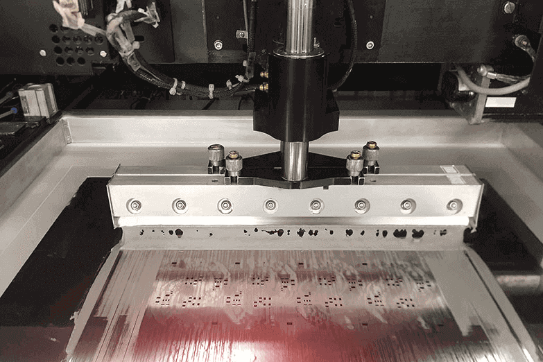
Making the aperture larger than the pad increases the volume, and it prints paste onto the soldermask around the pad. The paste that lands on the mask does not wet and forms a ball during reflow.
The usual compromise is an aperture that extends slightly beyond the pad in one direction only, with the mask dam respected on the other. Where the pad spacing allows, this is enough to make up the deficit.
An oversized aperture also affects the placement of the connector, since the paste must support the pin until reflow. A thick deposit with a marginally placed pin can be pushed aside. Our solder defects notes describe how the resulting balls appear.
Stencil Thickness and Stepping
The aperture volume is proportional to the stencil thickness, so a locally thicker stencil is a direct solution. The step is machined or formed into the stencil, and it increases the cost and the fragility of the tool.
A step also creates a transition that can catch the squeegee, so the geometry must be designed to allow the blade to ride over it. The step should be positioned where the aperture density is low.
The alternative to stepping is a second printing operation with a thicker stencil over the through-hole area only, which requires a second machine pass and precise alignment to the first print.
Pin Geometry and Fit
The clearance between the pin and the hole determines how much solder the joint needs and how easily the paste is displaced when the connector is placed. A tight fit leaves a small volume to fill and restricts the paste’s escape.
A loose fit requires more solder and allows the connector to move before reflow. The hole should be sized for the pin with the plating thickness accounted for, and the connector should be located by the paste rather than by hand pressure.
Our quality notes describe the hole and pin measurements that are checked on the first article.
Reflow Profile and Fill
The solder must be molten long enough to flow into the barrel and form fillets on both sides. A profile with a short time above liquidus produces a joint that is filled on the top and hollow in the middle.
The soak stage matters because the paste in the barrel must heat through the board thickness, which is slower than heating a surface deposit. The profile developed for the surface mount parts may be too short for the through-hole joints.
A longer time above liquidus increases the intermetallic growth, so the trade must be made deliberately. Our design release checklist notes where the profile requirement is recorded.
When It Is Not the Right Answer
Where the required volume exceeds what can be printed, the alternatives are a wave or selective soldering, or a solder preform placed in the hole before the pin is inserted.
Where the connector is large and heavy, placing it before reflow risks movement and requires staking or a fixture. A heavy connector soldered by a wave after the surface mount parts are in place is easier to control.
Where the connector must be added after reflow for thermal reasons, pin in paste is not applicable at all.
Verification
The verification is a section through a pin joint showing the fill and the fillet on both sides, on the first article and on a sample from production.
The paste volume printed for the through-hole apertures should be measured separately from the surface mount apertures, because the requirement is different and an average over the whole board hides both.
The joint should also be checked for voids, which are more likely in a deep barrel where the flux volatiles have a long path out.
Process Control and Verification
On a design of this kind, paste volume is the item that decides how the rest of the board is arranged. Keeping a sample from the panel turns a dispute into a measurement, because the same coupon can be re-examined by both parties without rebuilding the batch. Reviewing the design before the data is released is cheaper than correcting it after the panel is in the tank, because every step downstream inherits the decision made at the front end.
Documenting the assumption is part of the design work, and a short note on the drawing prevents a question that would otherwise arrive a day later and cost a day of schedule. The process window is set by the narrowest step in the flow, so an improvement anywhere else shows up as margin rather than as yield until that step is addressed.
Process Control and Verification
On a design of this kind, paste volume is the item that decides how the rest of the board is arranged. Keeping a sample from the panel turns a dispute into a measurement, because the same coupon can be re-examined by both parties without rebuilding the batch. Reviewing the design before the data is released is cheaper than correcting it after the panel is in the tank, because every step downstream inherits the decision made at the front end.
FAQ
Does pin in paste work for every connector? No. It suits connectors with a modest pin count and a hole volume that a practical aperture can fill, which is usually a board of moderate thickness.
Can a preform be used with a pin in paste process? Yes, and it is the standard answer where the printed volume is insufficient. The preform is placed in the hole before the pin is inserted.
What does gopcb provide for pin in paste? We provide the volume calculation from the hole, pin and board thickness, aperture and stencil thickness recommendations including stepping where needed, profile development for the through-hole joints, and sections that show the fill on both sides.