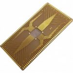
Edge Plating and Castellated Holes for Module Edges
A small module that must be soldered to a mother board along its edge uses half holes rather than pins. The castellations are drilled and plated as part of the board, then cut in half when the module is separated from its panel.
What a Castellated Hole Is
A castellated hole begins as a plated through hole near the board edge. After plating and finishing, the module is routed or sawn through the hole centres, leaving a half cylinder of plated copper on the edge of the module.
The result is a solderable feature on the edge that takes a fillet from the mother board, forming both a mechanical and an electrical connection.
The advantage over a connector is height and cost. The advantage over an edge connector is that the connection is soldered and does not depend on contact pressure.
Design Rules for the Drill
The hole diameter must be large enough to be plated reliably and small enough to suit the pitch. A typical arrangement has holes on a pitch of one to two millimetres with a finished diameter of half the pitch.
The holes must be placed with their centres on the intended module edge, because the cut passes through the centre. A hole that is offset from the cut line produces a castellation that is wider on one side and may be cut away entirely.
The plating specification must be stated. Our fabrication notes describe how the requirement is documented.
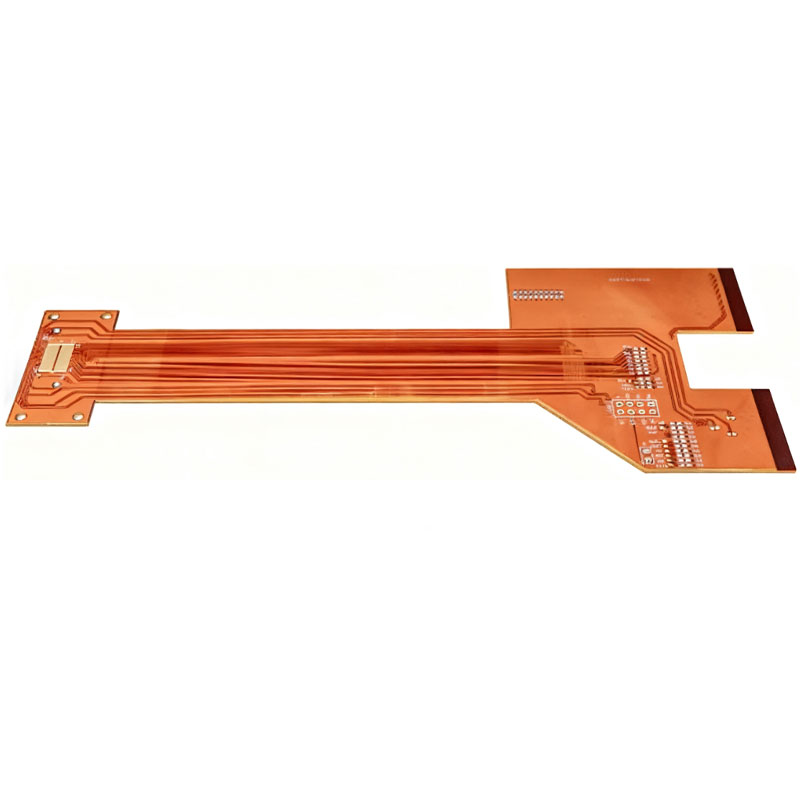
Edge Plating and Its Relationship
Edge plating is the related process in which copper is deposited along a cut edge, usually for a shielding connection rather than for a solder joint. It is performed before the final routing, and the resulting copper wraps the edge.
A castellated edge is different because the copper is the remnant of a hole, so its thickness is the plating thickness rather than a deposited layer.
Both processes require the copper to survive the routing operation without tearing. The adhesion of the copper to the laminate is what determines that, and a poorly bonded plating will lift at the edge. Our multilayer processing notes describe the related handling requirements.
Routing, Tolerance and the Cut
The module is separated by routing with a cutter that is narrower than the gap between modules, or by sawing. The cut must be positioned so that it passes through the hole centres within a tolerance that leaves an acceptable castellation on each side.
The tolerance of the cut relative to the drill pattern is the controlling tolerance, and it is a fabrication capability rather than a design choice. The design should leave enough castellation width that the tolerance does not consume it.
Where the panel uses a breakaway tab for the separation, the tab must not be placed across a castellation. Our board outline notes describe how the outline and the cut are toleranced.
Soldering to the Mother Board
The castellation takes solder from a pad on the mother board, and the pad must be large enough to form a fillet against the half cylinder. The fillet is what provides the mechanical strength.
The module sits flat on the mother board, so the castellated edges are on the sides rather than under the module. The fillet forms on the outside of the joint, which means it is visible and inspectable.
Where the module is placed in a recess so that its edges are not exposed, the joint cannot be inspected and the design should be reconsidered. Our quality notes describe the inspection criteria for the fillet.
Pitch, Current and Mechanical Load
Each castellation carries the current that the pad can carry, which is limited by the plating thickness and the width of the remaining copper. A castellated edge is therefore a poor choice for high current per pin.
Mechanically, the castellations resist shear and tension through the fillets. A module that will be subject to bending must have enough castellations that each carries a share of the load, and the module should be supported along its length.
Where the module is large, the number of castellations grows with the pitch requirement, and the design must balance the electrical needs against the space the pads consume on the mother board.
Process Considerations for the Module
The module is assembled and tested before separation, which means the panel must be handled with the modules attached. The separation step is the last operation in the module’s flow.
After separation, the castellation is bare copper unless it was finished. The finish must be applied before separation, so the plating that covers the hole wall is the finish that will be soldered.
Castellations that are left with an exposed copper edge after the cut will oxidise and become difficult to solder, which is why the finish selection and the storage of the separated module both matter.
Additional Considerations for This Build
Practical attention to castellated holes pays for itself here, because it decides whether the finished board behaves as the drawing intended. Where the requirement is not stated on the fabrication drawing or in the assembly notes, the shop has to assume a default, and that default is rarely the value the design was simulated with. Stating castellated holes explicitly, together with the tolerance that applies, removes the assumption and keeps the result predictable from batch to batch.
Process Control and Verification
On a design of this kind, module is the item that decides how the rest of the board is arranged. Where the requirement is not written down, the shop supplies its own default, and the default is chosen for the process rather than for the design. The measurements that matter are the repeatable ones: conductor width and spacing, annular ring, finished hole size, plating thickness and surface finish are all verifiable on a coupon that travels with the panel.
Running a first article through the same checks as the production panel confirms that the two agree, and that comparison is the cheapest form of process control available at prototype stage. Keeping a sample from the panel turns a dispute into a measurement, because the same coupon can be re-examined by both parties without rebuilding the batch.
Process Control and Verification
On a design of this kind, module is the item that decides how the rest of the board is arranged. Where the requirement is not written down, the shop supplies its own default, and the default is chosen for the process rather than for the design. The measurements that matter are the repeatable ones: conductor width and spacing, annular ring, finished hole size, plating thickness and surface finish are all verifiable on a coupon that travels with the panel.
FAQ
Can a castellated module be reworked? It can be removed with hot air or a soldering iron and replaced, since the joints are accessible. Removing it without damaging the mother board pads requires care.
Is edge plating the same as castellation? No. Edge plating deposits copper along a cut edge, while a castellation is the remnant of a plated hole cut through its centre.
What does gopcb provide for castellated modules? We provide drill and cut line geometry with the tolerance relationship, plating and finish specification for the castellation surface, panel layouts that keep the separation clean, and inspection of the separated modules. Where the cut tolerance cannot leave an adequate castellation, we propose a different connection method.