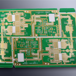
Drop Test for Board Level Assemblies: Setup and Failure Modes
A drop test reproduces the mechanical shock a product sees when it is dropped, and at board level it is used to compare designs, materials and processes rather than to certify a finished product. The test is short, the equipment is modest, and the failure it produces is a cracked solder joint that only appears under the right combination of acceleration and board flex.
What a Drop Test Measures
The measurement is the response of the assembly to a defined shock pulse, expressed as acceleration over time at a defined point. The pulse is described by its shape, its peak and its duration, and all three are needed to reproduce the condition. What matters for the board is not the peak figure alone but how the pulse excites the board and how much it bends in response.
A board that is bolted at four corners and struck in the middle will flex, and the flexure puts strain on the joints at the mounting points and at the corners of large packages. The test is therefore a measurement of the assembly as a system, not of the component alone. Two assemblies with identical components can behave completely differently under the same pulse.
The Physics of a Board Level Drop
When the fixture stops, the board keeps moving, and the inertia of the components loads the joints. The peak force at a joint depends on the mass of the component, the acceleration and the stiffness of the board beneath it, so a heavy part on a thin board is the worst combination. Doubling the mass of a component roughly doubles the load its joints have to carry.
The board then oscillates at its natural frequency, and the joints see a series of cycles rather than a single event. That is why the pulse duration matters as much as the peak, because a pulse that matches the natural frequency of the board transfers far more energy than one that does not. Damping from the enclosure, the coating and the mounting hardware all shift that frequency.

Fixtures and Mounting
The fixture defines the boundary conditions, so the same board tested in two fixtures gives two different results. Screw positions, support posts and the stiffness of the fixture itself all change the way the board bends, and the fixture used must be recorded with the result.
A standard fixture is used within one organisation so that results can be compared between designs and between suppliers. Where the fixture has to be built for a specific board, the mounting points should represent the way the product is actually supported rather than a convenient arrangement. Where a product has a compliant mounting, reproducing that compliance matters more than reproducing its stiffness.
Acceleration, Pulse Shape and Duration
Shock is normally specified as a half sine pulse with a peak acceleration and a duration, and both figures have to be controlled. A short pulse at high acceleration and a long pulse at lower acceleration can produce very different damage in the same assembly. The duration relative to the natural period of the board explains most of that difference.
The pulse is generated by dropping the fixture onto a pad or by a shock machine, and it is measured with an accelerometer mounted on the fixture rather than on the board. The board response is then measured separately, which is what shows whether the fixture or the assembly is dominating the result. A fixture that is too flexible absorbs energy and makes the assembly appear tougher than it really is.

Instrumentation and Data
The useful instrumentation is a set of strain gauges on the board and an accelerometer on the fixture, sampled fast enough to capture the event. A strain gauge beside a critical component shows directly how much the board bent there, which links the test condition to the failure. Sampling rate is not a detail, because a pulse lasting a millisecond cannot be resolved by a slow logger.
Electrical continuity monitoring during the test turns a mechanical test into a reliability test. A daisy chained component that shows a resistance spike during the drop has been damaged even if it passes a continuity check afterwards, and that event is the most useful data the test produces.
Failure Modes and Where They Appear
The classic failure is a crack at the interface between the solder and the component termination, on the side that is in tension as the board bends. Large packages fail before small ones, and parts near the board edge or near a mounting screw fail before those in the middle. The pattern is repeatable enough that the location of the first failure becomes a useful design indicator.
Another common mode is a crack in the laminate under a pad, which leaves the joint intact but the pad detached. Our solder defect notes describe how those fractures appear in section, and x-ray inspection shows the ones that cannot be seen optically.
Design Measures That Improve Survival
The measures that help are mostly mechanical. Reducing board flex by adding stiffeners or mounting points, moving heavy components away from high strain areas and choosing packages with compliant terminations all raise the survival margin without changing the electrical design.
Underfill and corner bonding also help for area array packages, by transferring load from the solder into the adhesive. The choice depends on how much rework the assembly has to tolerate, because an underfilled package is difficult to replace. Our component reliability notes describe the trade off. Corner bonding is easier to rework than a full underfill and captures much of the benefit for a large package.
Correlation With Product Level Testing
Board level results do not replace a product level drop test, because the enclosure, the mounting and the mass distribution all change the load path. What they provide is a fast and repeatable comparison that can be run during development, long before a product level sample exists.
The correlation between the two is usually established by testing the same design in both ways and adjusting the board level condition until the failure modes match. Once that relationship is known, the board level test becomes a useful proxy for design decisions. The correlation has to be re-established whenever the enclosure or the mounting changes significantly.
Reporting and Acceptance
A report should state the fixture, the mounting points, the pulse shape and duration, the number of drops and the electrical monitoring method, together with the failures observed and where they occurred. Without that detail the result cannot be reproduced or compared with anything.
Acceptance should be written as a pass or fail criterion rather than as an impression. Our laminate material properties notes describe the material contribution, and our judging PCB quality guidance describes how the evidence is recorded. Stating the criterion in advance also prevents a marginal result from being argued in either direction afterwards.
FAQ
How many drops are needed? Enough to produce a failure in a known position or to demonstrate that none occurs within a defined number of events. Six to twelve drops per condition is a common starting point for comparative work.
Does a heavier board survive better? Not necessarily. A thicker board flexes less, which helps, but it also carries more mass and transmits more energy to the joints at the mounting points, so the result depends on the whole assembly.
How does gopcb support drop testing? We supply boards with daisy chained test components, keep the stack-up and the copper balance within the agreed limits so that stiffness is repeatable, and work with the customer to interpret failures that are traced back to the board rather than the assembly.