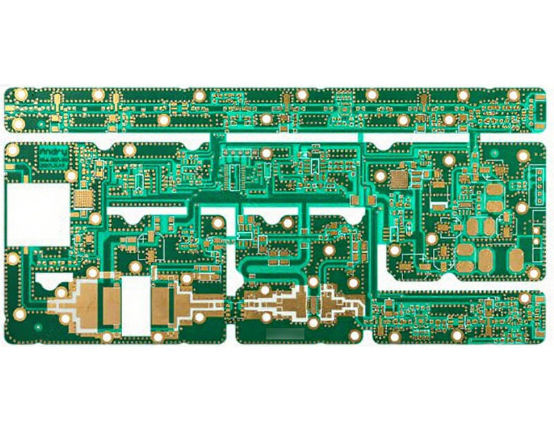
Wave Soldering Process Guide for Through Hole Boards
Wave soldering remains the standard way to attach through hole components at volume, and the process has changed less than the surface mount line beside it. What decides the result is still the flux, the preheat, the wave and the way the board leaves it.
Where Wave Soldering Still Fits
A wave machine is fast and cheap per joint for a board that carries connectors, transformers, terminals and a few surface mount parts on the same side. It solders every through hole joint in one pass, which no selective process can match for throughput.
The process suits a board that is designed for it: components on one side, pins that protrude a controlled amount, and a layout that keeps the solder from being shadowed by a tall body. A board that ignores those requirements cannot be rescued by adjusting the profile.
The Sequence in Order
The board is loaded onto a pallet or a finger conveyor, flux is applied, the assembly passes over a preheat stage, it crosses the solder wave and it leaves the wave at an angle that lets the alloy drain back into the pot.
Each stage prepares the next. Flux that has not been dried by the preheat will spatter in the wave, and a board that leaves the wave too slowly will hold solder between pins that should have separated.
Flux Application
Flux removes the oxide from the copper and the pin and keeps it from reforming while the joint is made. It has to be applied evenly and thinly, because a heavy deposit leaves residue that has to be cleaned and a light one leaves oxide that the wave cannot wet.
Spray fluxing with a low solids, no clean chemistry is the usual choice today. The deposit is measured by weight per unit area rather than by eye, since a variation across the panel shows up later as a difference in joint quality from one edge to the other.
Preheat
Preheat drives the solvent out of the flux and brings the assembly close to the temperature of the wave, so that the thermal shock at the solder is small. It also activates the flux so that it can do its work as the joint forms.
A typical entry temperature is in the region of ninety to one hundred and ten degrees on the top side of the board, with the exact value depending on the flux and the thermal mass. Too little preheat produces blowholes and spatter; too much consumes the flux before the wave arrives.
<img src="https://www.gopcba.com/wp-content/uploads/2026/08/pcb-assembly-image.jpg" alt="Through hole solder fillets on the top side of a wave soldered board” />
The Wave Itself
Solder is pumped through a nozzle to form a standing wave, and the board passes across it so that the alloy contacts the underside and fills each hole. The contact length and the wave height set the time each joint spends in the alloy.
Many machines use two waves. The first is turbulent and drives solder into the barrels and around the pins, while the second is smooth and removes the excess. A single wave can work, but the two wave arrangement gives more tolerance to component geometry and hole size.
Exit and Drainage
The joint is formed as the board leaves the wave, not while it is in it. The conveyor angle, the speed and the solder temperature together decide how the alloy separates from the pins and whether icicles or bridges remain.
If the board leaves level, the alloy stays connected between adjacent pins until it freezes, which is the classic bridge. A slight upward angle lets gravity help, and the correct combination of angle and speed is established during the profile trials rather than guessed on the line.
Fillets and Joint Quality
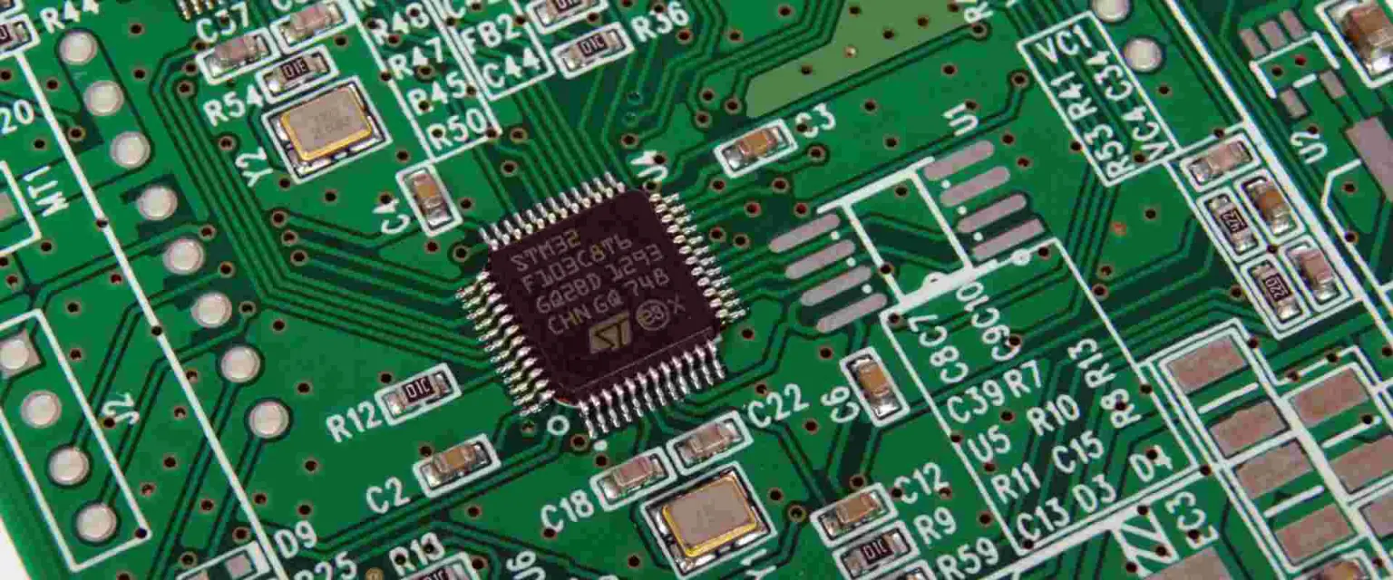
A good through hole joint shows a concave fillet on the top side of the board and full fill in the barrel, with a smooth, bright surface that wets the pin and the pad. A joint that has wetted the pin but not the pad indicates that the pad was oxidised or that the flux was consumed too early.
The top side fillet is the visible indicator that the barrel filled correctly. Where the solder has risen only part way, the cause is usually preheat, flux or hole diameter rather than the wave temperature alone.
Defects and Their Causes
Bridging comes from too much solder, an exit angle that is too flat, or pads that are too close for the process. Insufficient fill comes from poor flux coverage, cold pads, contaminated alloy or a barrel that is too small for the pin.
Blowholes and spatter come from moisture and from flux that was not dried. Dross, the oxide that forms on the surface of the pot, causes roughness and should be removed on a schedule, since it also changes the wave shape as it accumulates.
Fixtures and Pallet Design
A pallet holds the board flat, keeps components that cannot be immersed away from the wave and protects parts that would be shadowed. It also limits the distortion of a thin board as it is heated, which improves the consistency of the fill.
Material choice for the pallet matters: the fixture has to survive the temperature, hold its flatness and not absorb flux. A warped pallet produces the same effect as a warped board, and the operator will look at the wrong one first.
Wave, Selective and Reflow Compared
Selective soldering uses a small nozzle to solder individual joints and suits mixed assemblies where the through hole parts are few. Reflow with pin in paste allows those parts to be soldered in the same oven as the surface mount devices.
Wave soldering remains the fastest option for a board with many through hole joints, and the cheapest per joint. The choice between the three methods is a matter of joint count, thermal sensitivity and whether the assembly can tolerate the immersion. The single joint case is covered under through hole soldering, and the alloy choice under lead free and leaded alloys.
Process Control and Verification
On a design of this kind, reflow is the item that decides how the rest of the board is arranged. Documenting the assumption is part of the design work, and a short note on the drawing prevents a question that would otherwise arrive a day later and cost a day of schedule. The process window is set by the narrowest step in the flow, so an improvement anywhere else shows up as margin rather than as yield until that step is addressed.
Process Control and Verification
On a design of this kind, reflow is the item that decides how the rest of the board is arranged. Documenting the assumption is part of the design work, and a short note on the drawing prevents a question that would otherwise arrive a day later and cost a day of schedule. The process window is set by the narrowest step in the flow, so an improvement anywhere else shows up as margin rather than as yield until that step is addressed.
Alloy and Pot Maintenance
The alloy in the pot is a consumable with a specification. Its composition drifts as solder is removed on boards and as elements dissolve from the surfaces it touches, and a copper level that rises beyond the limit changes the melting behaviour and the appearance of the joint.
Pot maintenance is therefore a scheduled task: skim the dross, sample the alloy for analysis, top up with the correct grade and record the result. A pot that is never sampled will still solder, but the window between good and marginal narrows until a batch fails without warning.
Contamination and Its Symptoms
Contamination enters the process from several directions. Handling residues on the board, flux that has polymerised on the fixture, oils from the conveyor and airborne dust all end up in the pot or on the surface being soldered, and each has a different symptom.
The most useful diagnostic is a comparison between the first and last boards of a run. A defect that grows through the shift points at the pot or the flux system, while one that is constant suggests the design or the board itself rather than the machine.
FAQ
Why does a joint show a fillet on top but a hole that is only half filled? Usually because the hole is too large for the pin or the preheat is too high, so the flux has been consumed before the wave arrives.
How is the flux deposit controlled? By measuring the weight per unit area on a test plate and comparing it with the specification for the chemistry in use.
Should the pallet be cleaned? Yes. Flux and dross accumulate on the fixture and change the thermal behaviour of the next board. Material management for the line is covered under SMT material management.