Four Wire Kelvin Measurement of PCB Trace Resistance
Measuring the resistance of a copper trace looks straightforward until the number matters. A trace a few centimetres long may have a resistance of a few milliohms, and the probe contact resistance in a two wire measurement can be larger than the value being measured. Four wire, or Kelvin, measurement removes that error from the result.
Why Two Wire Measurement Fails
In a two wire measurement the same probes carry the current and sense the voltage, so the voltage measured includes the drop across the probe contacts and the leads as well as across the trace. With a contact resistance of a few milliohms per probe, the error can easily exceed the true value.
The problem grows as the resistance being measured falls. For a modest trace, the contact resistance is a percentage error; for a plated via or a solder joint, it can be the dominant term. Reporting a two wire result as trace resistance is therefore misleading whenever the value is small. The same reasoning applies to any measurement where the connection itself is a significant part of the total, such as a plated hole, a crimped joint or a connector contact.
How Four Wire Measurement Works
Four wire measurement separates the two functions. One pair of probes carries a known current through the trace, and a second pair measures the voltage across it. Because the voltmeter has a very high input impedance, almost no current flows in the sense circuit, and the voltage drop across the sense contacts is negligible.
The result is the resistance of the trace between the two sense points, independent of the contact resistance of the current probes. The residual error comes from the sense contact resistance divided by the meter input impedance, which is small enough to ignore in nearly every practical case.
Kelvin Sensing in Practice
The technique is named after Lord Kelvin, who used it for low resistance measurement, and the term Kelvin connection is now used for any arrangement with separate current and sense paths. It appears in a wide range of equipment, from bench meters to the test points on a shunt resistor.
The principle is the same everywhere: force current through the outer pair, sense voltage across the inner pair, and place the sense points inside the current points. Reversing the order produces a result that includes part of the current path and defeats the purpose.
Contact Resistance and Probe Choice
Contact resistance depends on the probe material, the tip geometry, the contact force and the cleanliness of the surface. A sharp probe penetrating an oxide layer gives a lower and more repeatable contact resistance than a blunt one resting on the surface, which is why spring loaded test probes are specified with a minimum force.
Where the same probes are used repeatedly, the contact resistance changes as the tips wear and as they pick up contamination. In a four wire setup the effect on the final measurement is largely removed, but a poor contact on the current pair still limits the current that can be forced, which reduces the resolution of the result.

Test Point and Pad Design
Four wire measurement requires four connection points, or a pad geometry that allows the current and sense probes to land separately. A test point designed for this has the sense connection placed inside the current connection, with enough separation that the probes do not touch each other.
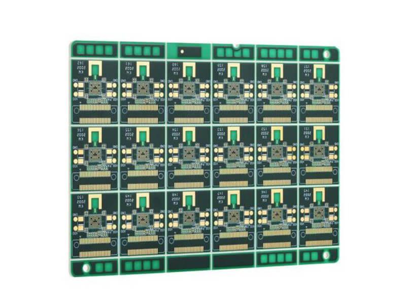
On a production board, a dedicated test coupon in the panel border is the usual solution, with traces of defined length and width and pads sized for the probes. That gives a measurement of the process rather than of a particular product trace, and it can be repeated on every lot to show a trend.
Measuring Very Low Resistance
Very low resistance demands more than four wires. Thermal voltages at the junctions between dissimilar metals appear as an offset, and they can be larger than the signal being measured. Current reversal, where the measurement is taken with the current in each direction and the two results are averaged, cancels most of that offset.
Resolution also matters. A meter reading to four digits on a range of a few milliohms has a resolution far coarser than the changes that are usually interesting, so the range must be chosen for the value being measured rather than for convenience. Averaging several readings also helps, because it reduces the effect of random noise on a signal that is already small.
Temperature and Stability Effects
Copper resistance changes by roughly four tenths of a percent per degree Celsius, so a one degree change in board temperature alters the result by more than many of the effects being investigated. Measurements should be taken at a recorded temperature, and comparisons should be made at the same temperature.
Self heating is the related risk. Forcing a large current through a small trace raises its temperature, which raises its resistance while the measurement is being taken. The current should be limited to a level that produces a negligible temperature rise, and the reading should be stable before it is recorded.
Applications in Board Testing
Four wire measurement is used for trace resistance on a coupon, for via and barrel resistance, for solder joint resistance and for the resistance of plated features where the thickness has to be inferred. It is also the basis of the measurements used to characterise current sense shunts.
On production boards it is normally applied with flying probe or a dedicated fixture, where the probe arrangement can be designed for four wire contact. The comparison between the two approaches is described in this guide to flying probe testing, and both depend on a probe contact that is good enough to force the required current.
Setting Up a Repeatable Measurement
A repeatable method fixes the current, the probe positions, the temperature, the reading time and the number of readings. Once those are fixed, the measurement can be compared across operators, across machines and over time, and the residual variation reflects the process rather than the method, which is the same principle applied to inspection in this guide to judging PCB quality.
The method should also state what the result represents. The resistance measured between two sense points on a trace includes the trace and any vias or connectors between them, and a result quoted without that context cannot be compared with any other. Where the value is being used to infer plating thickness, the relationship between resistance and thickness should be established on the same geometry, as described in this guide to plating thickness measurement.
FAQ
When do I need four wire instead of two wire? Whenever the resistance being measured is comparable to the contact resistance of the probes, which in practice means anything below a few ohms and certainly anything in the milliohm range. Above that, two wire measurement is simpler and adequate.
Can four wire measurement be done with a normal multimeter? Not with a two terminal meter. It requires a meter with separate source and sense terminals, or a dedicated milliohm meter. Some handheld meters offer a four wire mode, and those can be used if the leads and probes are suitable.
Why does my reading keep drifting? Temperature is the usual explanation, either from the room, from handling or from self heating caused by the test current. Letting the board stabilise, reducing the current and recording the temperature will normally make the reading repeatable.